Measuring Turbidity, TSS, and Water Clarity – Environmental Measurement Systems
Mục lục
Measuring Turbidity, TSS, and Water Clarity
Turbidity and Total Suspended Solids Measurement Methods
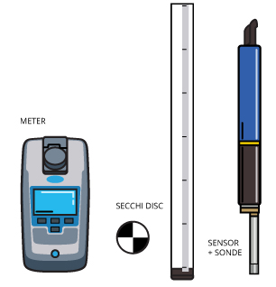
Turbidity, as an optical property of water, is one of the more difficult parameters to measure. How murky or opaque water is can be a subjective measurement 1. Based on the measurement method, different units have been defined to standardize turbidity levels and allow comparisons. Today, there are three modern methods for measuring turbidity, and two for measuring total suspended solids. These methods have expanded the range and accuracy of turbidity measurements from basic object visibility tests and historical visual extinction methods 2. However, each method has its advantages and limitations.
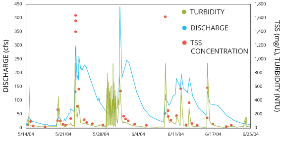
Turbidity is caused by particles and colored material in water. It can be measured relative to water clarity, or directly with a turbidity instrument such as a turbidimeter or turbidity sensor. Turbidity sensors may also be referred to as submersible turbidimeters 28. Water clarity methods involve a secchi disc or tube. They are often quick and inexpensive, but are only as accurate as the person using them 1. Turbidity meters use nephelometry (90 degree scattering) or other optical scatter-detection techniques for fast, accurate turbidity measurements on water samples. Turbidity sensors also use optical technology, but instead of using sample cells, they can be placed directly in the water source to measure turbidity. In addition, turbidity sensors can be used for continuous turbidity measurements 21,22,23. However, when using a meter or a sensor, most turbidity data are not inter-comparable. Turbidity units such as NTU and FNU have “no intrinsic physical, chemical or biological significance” 52. Thus differences in suspended sediment type (e.g. algae, clay or sand) and differences in instrument design will alter a turbidity reading. These instruments can be convenient and accurate tools as long as consistency is maintained.
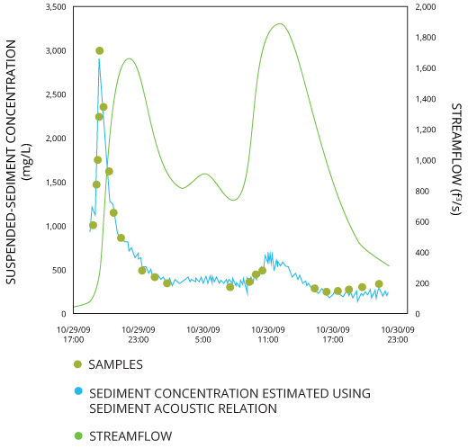
Total suspended solids (TSS) are the main cause of turbidity. The most common, and accurate, method of measuring suspended solids is by weight. To measure TSS, a water sample is filtered, dried, and weighed. This method is the most accurate technique for measuring total suspended solids, however it is also more difficult and time-consuming 3.
The second method is a recent development by the U. S. Geological Survey. This organization has developed a technique for calculating suspended sediment from acoustic Doppler meter backscatter 4. While this method is not as accurate as a weigh scale, it provides the opportunity for continuous suspended sediment measurements, just as turbidity sensors allow for continuous turbidity measurements. Total suspended solids can also be estimated from turbidity measurements, however, this requires linear regression modeling and must be re-calculated for each sampling period and location. No standard model exists due to the differences in stream flow, sediment concentration, and particle size 5.
A Note on Turbidity, Turbidity Units and Unit Conversions

As mentioned above, turbidity units have no inherent value. They are a qualitative, rather than a quantitative, measurement 54. There is no standard conversion between various turbidity units (e.g. NTU or FNU) and quantitative mass measurements (mg/L) 52. Furthermore, clear water is not always healthy, and likewise turbid water does not necessarily indicate an issue. Turbidity data must always be taken in context 54. This means that it is important to consider the nature of suspended solids that are present, in the larger picture of the water system (e.g. a stream, lake, ocean, or wastewater treatment plant). To this end, it is more often a change in turbidity that indicates an issue, such as the development of an algal bloom on a lake, or a steady increase in suspended sediment in a river due to a polluted tributary.
As a qualitative, contextual measurement, the variety of turbidity units in use can be confusing. Each measurement method uses a different unit. A multitude of turbidity units were introduced because a change in the type of light source, detector, or angle of measurement changes the turbidity reading. In addition, mineral-based solids will reflect more light, while organic particles tend to absorb more light 5. These effects are based on the relationship between light (wavelengths and beam width) and particle size, color and concentration 54. As such, different turbidity instruments can output various turbidity measurements even in the same sample 51.
While turbidity units can be approximately equal, to ensure accurate records, consistency in methods and instruments must be maintained. Historically, units such as NTU and JTU were often erroneously interchanged because they were assumed to be equivalent 55,56. Unfortunately, this practice still occurs today, particularly with FNU and NTU 57. Many instrument manuals suggest using inappropriate units simply because they are more well known. Which units should be used with which measurement method or instrument design can be found in the Quality Standards section.
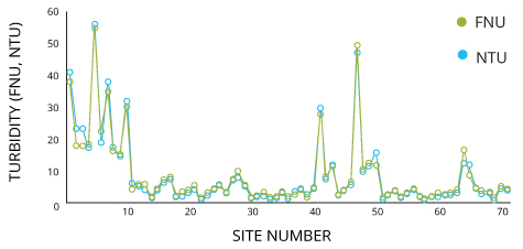
If the use of a particular unit is absolutely necessary, correlations between two turbidity instruments can be developed 18. These calculated models can be used to convert between units and compare data from different instruments when using the same sample or same surface-water location 54. Likewise, correlations can also be made between suspended sediment concentrations and turbidity measurements 5. However, these calculated models are only adequate for the specific location where measurements were made. Surface waters are not static, and turbidity levels and sources will vary by location, season or other factors 51,54. Thus, in other bodies of water with changed particle type, size, and distribution, such conversions are no longer accurate 54. New measurements must be taken to calculate a new conversion model for that location.
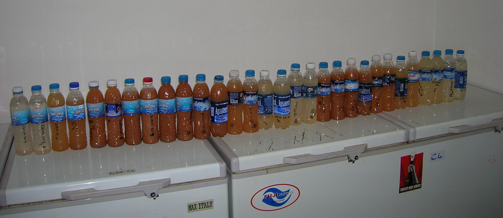
Correlations between total suspended solids or suspended sediment concentrations in mg/L and turbidity in turbidity units can be made with linear regression analysis, provided enough data is collected 5. In purely mineral-based samples, this relationship is expressed through the following equation 29:
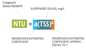
NTU = a * TSSb
NTU = Turbidity Measurement
TSS = Suspended solids measurement in mg/L
a = regression-estimated coefficient
b = regression-estimated coefficient, approximately equal to 1
When organic material, air bubbles or dissolved colored material is present, this equation can become inconsistent 29. In addition, the accuracy of the correlation is based on a linear relationship between turbidity and suspended solids 29. When the relationship becomes non-linear (above 40 NTU for nephelometric methods), the equation is no longer suitable. United States Geological Survey modeling uses streamflow data in addition to turbidity and suspended sediment measurements to calculate regression models. The USGS recommends using base-10 logarithmic transformation to meet linear regression assumptions 58. Transforming the data improves symmetry, linearity and normality, though it also requires a retransformation bias correction factor 58. An example of a linear regression model through this method may look like:
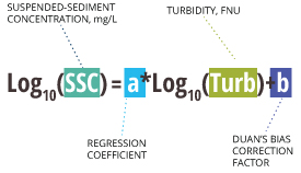
Log10(SSC) = a *Log10(Turb) + b
SSC= suspended-sediment concentration, in mg/L
Turb= turbidity, in formazin nephelometric units (FNU)
a= regression coefficient
b= Duan’s bias correction factor
Once a regression model has been accepted, it can be used to predict suspended sediment concentrations 58. The model should be re-analyzed and validated as necessary, based on the nature of the surface-water source. If a single linear regression model does not meet established criteria, a multiple regression model can be used 58. Though no standardized formula exists, these calculated correlations can be useful in monitoring water quality 52. Care should be taken when when establishing relationships between turbidity and suspended sediment as the values of both in a body of water may constantly change 51.
Quality Standards
To further complicate turbidity measurements, there are several water quality standard methods and design standards in use. The United States Environmental Protection Agency has approved eight standards for monitoring drinking water 41. Until 2009, only four methods were accepted: USEPA Method 180.1, Standard Method 2130B, Great Lakes Instrument Method 2 (GLI 2) and Hach Method 10133 18. In 2009, the USEPA approved four new methods: Mitchell Methods M5271 and M5331, Orion AQ4500, and AMI Turbiwell 40.
The United States Geological Survey uses, but does not require, some EPA-approved methods, as non-regulatory methods can be more accurate at higher turbidity levels 18. Common USGS methods are: International Organization for Standardization (ISO) 7027, Standard Methods 2130B, USEPA Method 180.1, and GLI Method 2 6. The ADCP backscatter method is also gaining traction for monitoring total suspended solids specifically 4. However, when monitoring drinking water, the USGS states that EPA-approved methods must be followed 18.
Of all of these methods, the EPA Method 180.1 and the ISO 7027 are the most well-known guidelines and are internationally recognized when verifying turbidity meter and turbidity sensor performance and method compliance 14. Outside of the U.S., the ISO 7027 method is king 28. The American Society for Testing of Materials considers several of these methods as appropriate and recommends instruments utilizing the respective technologies based on turbidity level 19,20. However, ASTM D7315 is very specific about reporting procedures – units must indicate exactly which instrument design is being used 19,24.
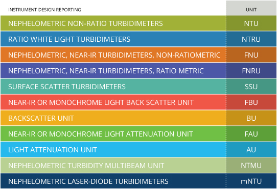
Other instrument-based methods for measuring turbidity include: light attenuation, surface scatter, and backscatter 19. While turbidimeters and spectrophotometers using these designs exist, they do not comply with any of the above standards. To ensure accurate reporting when using a ratiometric turbidity meter or backscatter-based turbidity sensor, the ASTM D7315 unit reporting protocol should be referenced 24.
EPA Method 180.1
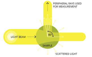
Method 180.1, Determination of Turbidity by Nephelometry is the United States Environmental Protection Agency’s standard for turbidity meter design. The standardized criteria attempt to ensure both accuracy and comparability between compliant meters 15. Instruments in compliance with the EPA Method 180.1 use Nephelometric Turbidity Units (NTU) 15.
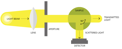
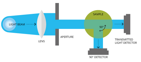
This method uses nephelometric technology, which measures light scatter at at 90-degree angle from the initial light path 16. The photodetector must be centered at that angle, and cannot extend more than 30 degrees from that center point. To minimize differences in light scatter measurements, the method states that the incident and scattered light cannot travel more than 10 cm from the light source to the photodetector 15. Additional photodetectors are permitted under this method, provided that the 90-degree angle is the primary detector.
EPA Method 180.1 further requires that the light source used in each turbidity meter be a tungsten lamp with a color temperature between 2000 K and 3000 K 15. This means that the tungsten output is polychromatic, or broadband in spectrum. When the light reaches the photodetector, the spectral peak response should be between 400-600 nm. The use of a wide spectral band means that the turbidity meter may be affected by colored samples. As dissolved colored matter can absorb some wavelengths, the accuracy of the meter may decrease 16. However, a broadband spectrum also allows the meter to be sensitive to smaller particles. This sensitivity means a tungsten lamp source will provide a more accurate response than a monochromatic light source when measuring a sample with very fine particles 16.
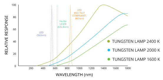
The use of a tungsten lamp as a light source requires a daily calibration check and frequent recalibration 16. This is due to the incandescent decay inherent in the lamp. As the lamp slowly burns out, much like any other incandescent light bulb, the light output will decrease as well, altering the measurement reading 16. Frequent recalibration minimizes any errors due to light decay.
Instruments in compliance with the EPA Method 180.1 are suitable for measuring turbidity levels between 0-40 NTU (nephelometric turbidity units). These turbidity meters should have a resolution of 0.02 NTU or better in water with a turbidity of less than 1 NTU 15. However, these turbidity meters will not be as accurate at turbidity levels above 40 NTU. At higher levels, the relationship between light scatter and turbidity becomes non-linear. This means that the amount of scattered light that can reach the photodetector decreases, limiting the capabilities of the instrument 16. Instead, these instruments are best used when monitoring treated water, as there is little color interference and limited turbidity.
The EPA Method 180.1 does allow for dilution if the sample is over 40 NTU 6. Once the sample is diluted below 40 NTU and remeasured, the new reading is multiplied by the dilution factor to calculate the turbidity of the original sample 31.
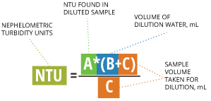
NTU = (A * (B + C)) / C
A = NTU found in diluted sample,
B = volume of dilution water, mL, and
C = sample volume taken for dilution, mL.
ISO 7027
The International Organization for Standardization developed a stricter design standard known as ISO 7027 Water Quality—Determination of Turbidity 16. This design standard attempts to ensure that turbidity sensors and meters in compliance with this method would have good repeatability and comparability 16. While it is in common use across Europe, this method is not approved by the USEPA for drinking water regulations 18.
Best known for its requirement of a monochromatic light source, ISO 7027 eliminates most color interferences 18. However, there is some ambiguity and misdirection regarding instrument compliance in this area. This method specifically requires a monochromatic light source at a wavelength of 860 nm, with a spectral bandwidth of 60 nm 18. This allows the wavelength to vary +/- 30 nm from 860, for a light source range of 830-890 nm 32. While both LEDs and filtered tungsten filament lamps can be used as a monochromatic light source, they do not necessarily fall within the specified range. White-light LEDs do not meet the ISO 7027 requirements.
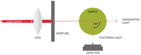
Furthermore, some instrument manuals and turbidity guides refer to the ISO light wavelength requirement as “Near-IR” 18. Near-IR, or near-infrared, encompasses the range of 780-900 nm, beyond the specifications of ISO 7027. While the near-IR range meets the same goals for the restricted light source, (reduced color interference and stray light error), it does not necessarily mean compliance 18. Most instruments in compliance with this method use a 860 nm LED light source 18.
The ISO 7027 method requires a primary photodetector angle of 90 degrees +/- 2.5 degrees 18. Additional detection angles are allowed (such as attenuation), but the nephelometric 90-degree detector must be the primary measurement source. The acceptance angle of the detector should extend 20-30 degrees (+/- 10-15 degrees)51. This is a more precise requirement than the EPA Method 180.1, which allows for +/- 30 degrees from the right angle 32. Like EPA Method 180.1, light path distance is limited to 10 cm (incident light + scattered light) 11.
For turbidities between 0-40 NTU, the recommended units for this method are Formazin Nephelometric Units (FNU) 18. This range can be extended by diluting the sample until it falls below 40 NTU, and then multiplying by the dilution factor. The USGS suggests that this method can be used up to 1000 NTU with a single photodetector, or up to 4000 NTU if multiple detectors are used (ratiometric) 18. If multiple detectors are used, units should be Formazin Nephelometric Ratio Units (FNRU).
Both EPA 180.1 and ISO 7027 use nephelometric technology calibrated by a formazin standard 14. However, the differences in light source and the slight differences in design create different measurement results. ISO 7027 has the advantage that near-infrared light is rarely absorbed by colored particles and molecules, reducing error that would be present with a broadband light source 18. Furthermore, LEDs tend to be more stable over time, requiring less calibration 45. However, as longer wavelengths are less sensitive to small particles, ISO 7027 will produce slightly lower turbidity readings than EPA 180.1 at low turbidities 32.
GLI Method 2
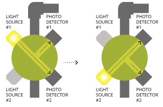
The Great Lakes Instrument Method 2 doubles the number of photodiodes and photodetectors used in the average turbidity instrument 16. It also doubles the number of measurements taken. As such, this design is also known as a modulated four-beam turbidimeter. By using two measurements, two light sources, and two detectors, this method can compare results between the detectors and cancel out errors 18.
This method requires 860 nm LEDs, which allows for color compensation, much as the single beam ISO 7027 method does 18. The LEDs alternate light pulses every half second. The photodetectors take simultaneous readings, providing an “active signal” and “reference signal” 16. The detector directly across from the active LED is considered the active signal, while the detector at a 90-degree angle is considered the reference signal. Every half second, the active and reference signals switch as the second LED pulses 16. Thus the GLI2 method provides two active and two reference measurements to determine each reading. The ratiometric calculations used to determine turbidity mean that the light input and the output are directly proportional. Any errors that may appear are thus mathematically canceled out 16.
A modulated-four beam ratiometric algorithm can use the following formula 37:
NTU = Calslope * Sqrt((Active1 * Active2) / (Reference1 * Reference2)) – Cal0

Calslope = Calibration coefficient
Active1 = 90 Degree Detector Current (Light Source 1 ON, Light Source 2 OFF)
Active2 = 90 Degree Detector Current (Light Source 1 OFF, Light Source 2 ON)
Reference1 = Transmitted Detector Current (Light Source 1 ON, Light Source 2 OFF)
Reference2 = Transmitted Detector Current (Light Source 1 OFF, Light Source 2 ON)
Cal0 = Calibration coefficient
As fouling, sediment or color interference affect both detectors equally, any potential errors are nullified 37.
Based on the ratiometric (directly proportional) algorithms used to calculate turbidity, the GLI2 method allows for increased sensitivity and error cancellation in the 0-100 NTU range 16. However, this method loses some accuracy as turbidity levels rise above 40 NTU 18. This is due to the the increased light intensity. As turbidity increases, the intensity of the scattered light will also increase 17. GLI2 instruments are ideal for lower turbidity ranges, and when measuring in the 0-1 NTU range in particular, they are extremely accurate 16.
Due to its multi-beam design, the USGS recommends using Formazin Nephelometric Multibeam Units (FNMU) instead of NTU as the turbidity units for this method 18. Instruments with this design are still classified under nephelometric technology as they use photodetectors at 90-degree angles.
Hach Method 10133
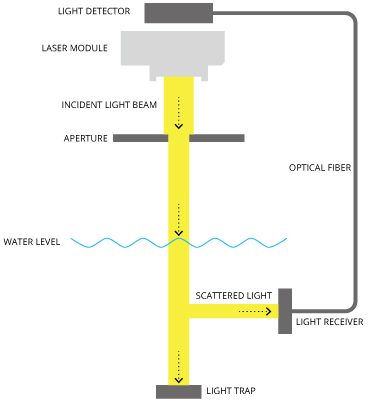
The Hach Method 10133 is an EPA-approved turbidity measurement method 18. While it is also based on nephelometric technology (90 angle), Hach Method 10133 uses a laser light source as opposed to a tungsten lamp or infrared LED. It is not recommended for use when turbidity levels exceed 5.0 NTU 30.
To be in compliance with this method, the laser diode must emit red light, with a wavelength between 630 nm and 690 nm 30. As with the EPA Method 180.1 and the ISO 7027 method, the total distance that the light beam travels cannot exceed 10 cm. The detector must be set at 90 degrees from the incident light path, and must be connected to a photomultiplier tube (PMT) via a fiber-optic cable 30. Fiber-optic cables may also be used to carry light from the diode to the sample 30. The PMT is used to increase the sensitivity of the photodetector. This setup is also considered an in-line or on-line process stream method as it uses sample lines instead of a sample cell or a dynamic instrument (in-situ turbidity sensor) 18,30.
With a laser diode as a light source, and photomultiplier tube connected to the detector, instruments in compliance with this method can detect extremely low turbidity levels 20. Due to the heightened resolution of this method, units for this method are expressed as milli-Nephelometric Turbidity Units (mNTU) (20). Thus the recommended range for these instruments is 0-5 NTU (0-5000 mNTU). Unlike the previous methods, Hach Method 10133 is not used with turbidity sensors or meters. It is designed for on-line, or process monitoring 30. Instruments in compliance with this method are ideal at very low turbidity levels, such as monitoring drinking water or effluent from wastewater treatment plants 18.
Standard Methods 2130B
Standard Methods 2130B (as it is today) was established by the American Public Health Association (APHA) in Standard Methods for the Examination of Water and Wastewater, 19th edition 32. Nearly identical to USEPA Method 180.1, Standard Methods 2130B clearly defines the basis of nephelometric technology, as well as the methods for creating a proper primary calibration standard 31. While the two methods are often interchanged, most instruments and reporting procedures default to the EPA Method 180.1, as it is more well known and more commonly used 32.
Established two years apart, (1993 and 1995 respectively), both the USEPA Method 180.1 and Standard Methods 2130B maintain the same physical requirements for compliant turbidity meters. Specifically, each method requires a tungsten-filament lamp light source with a color temperature of 2200-3000K 16,31. They also both require the photodetector to be centered at 90 degrees, and not to stretch more than 30 degrees from that point. The light path travelled by both incident and scattered light must be no more than 10 cm combined from the light source to the detector. Finally, the photodetector must have spectral response peak between 400-600 nm 31.
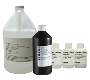
Despite all of the overlap, there are two minor differences worth noting between Standard Methods 2130B and USEPA Method 180.1. The first difference is the definition of primary calibration standard 11. According to Standard Methods, the only acceptable primary standard is formazin, made from scratch by the user, following the specific instructions outlined in this method 11. This includes the specified filter size of 0.1 um if the prepared formazin needs to be diluted (EPA Method 180.1 allows a filter size of 0.45 um) 31. However, method 2130B goes on to state that user-prepared formazin should be a last resort due to the use of carcinogenic compounds in its preparation 31. Instead, Standard Methods strongly recommends using a commercial or manufacturer-supplied calibration solution. These solutions, whether made from a commercial stock suspension of formazin, styrene-divinylbenzene copolymers, latex suspensions or other polymer suspensions are all considered secondary standards 31. The USEPA Method 180.1, on the other hand, considers user-prepared formazin, commercial formazin and AMCO-AEPA-1 styrene-divinylbenzene polymer standards all to be primary standards. Only manufacturer-supplied latex suspensions and metal oxide/polymer gel suspensions are called secondary standards by this method 31.

The second difference is in the measurement range of these methods. The USEPA Method 180.1 is limited to 0-40 NTU 32. Any samples with turbidities outside of this range must be diluted to below 40 NTU. The resulting measurement is then multiplied by the dilution factor to determine the original turbidity 31.
The 18th edition of Standard Methods (1992) also allowed this dilution method and included it as a step of the measurement procedure for samples with turbidities over 40 NTU 35. However, every edition since (starting with the 19th edition in 1995), has removed this step of the measurement procedure 31,33,34. Instead, the Standard Methods 2130B, as it is known today, goes beyond this range, allowing turbidity levels over 1000 NTU to be measured. The measurement procedures now specify that dilution is to be avoided whenever possible 31,33,34. Standard Methods explains that when a sample is diluted, the composition of the sample may change, rendering the resulting measurement less than accurate. Even so, as EPA Method 180.1 allows dilution, all Standard Methods 2130B (from the 18th edition through the 22nd) are considered USEPA approved 41,47.
Mitchell Methods M5271, M5331; Orion AQ4500; AMI Turbiwell
These four methods were approved as alternate test procedures for measuring turbidity in drinking water in 2009 by the USEPA. The term “alternate test procedures” (ATP), is used as these methods use the same technique as an EPA-approved method (nephelometry) without creating an entirely brand new method 42. To be approved, each method needs to produce comparative results relative to EPA Method 180.1 40.
Mitchell Method M5271
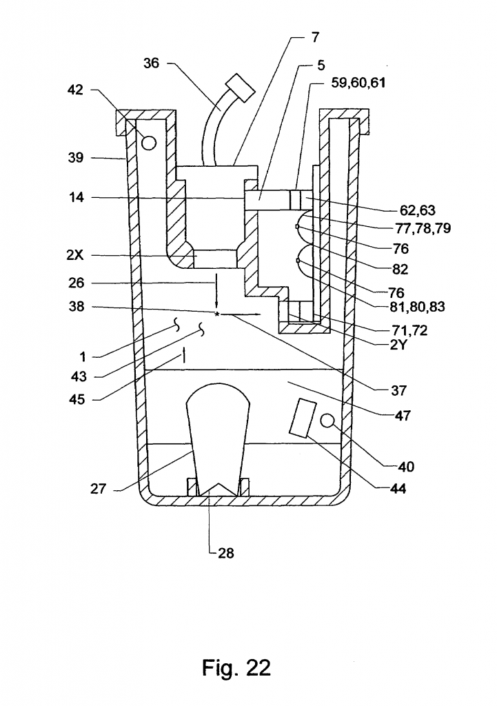
The Mitchell Method M5271 is similar to Hach Method 10133 as it uses laser nephelometry to determine turbidity in an on-line or process monitoring instrument. The laser light source must emit a wavelength of 650 +/- 30 nm 40. This is a shift of 10 degrees from the Hach method, which uses a laser diode at 630-690 nm. It is also very similar to EPA Method 180.1, as it limits light travel to 10 cm and allows the photodetector to extend +/- 30 degrees from the 90-degree center 40. This method does introduce some new technology, as it requires a bubble trap and anti-fog windows 43. To be compliant with this method, the turbidity sensor must be able to withstand up to 30 psig of pressure 43. Mitchell Method M5271 is applicable in the range from 0-40 NTU.
Mitchell Method M5331
The second Mitchell method – Mitchell Method M5331, does not use a laser. Instead, it requires an LED as a light source 40. The LED must emit a wavelength of 525 +/- 15 nm 44. All other requirements match Mitchell Method 5271 in terms of distance traveled by incident and scattered light, location and spread of the photodetector, and the use of a Mitchell/Mersch bubble trap and anti-fog windows 44. It also is applicable for turbidities between 0-40 NTU. Both Mitchell Method M5331 and M5271 are designed for process monitoring, or on-line continuous turbidity monitoring. On-line instruments usually divert a sample flow, with the sensing instrumentation submerged below the water 16. This design is appropriate for continuously monitoring drinking water or wastewater effluent.
Orion Method AQ4500
The Orion Method AQ4500 was developed by Thermo Scientific and is based on the use of their turbidity meter, Thermo Orion AQUAfast Turbidimeter Model AQ4500. This method follows all of the requirements of EPA Method 180.1 except for the specified light source. This method still requires a 90-degree photodetector with a spectral response between 400 nm and 600 nm, and incident and scattered light cannot travel further than 10 cm combined 40.
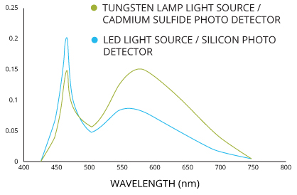
Instead of using a polychromatic tungsten lamp as a light source, the Orion method AQ4500 uses a “white” LED. To achieve a broadband output with a typically narrow band LED, this method uses a phosphorus coated blue LED 45. This expands the spectral output from the blue 450 nm wavelength to a wide spectrum response similar to a tungsten source/cadmium sulfide detector combination 45.
Furthermore, the use of an LED light source allows for rapid pulsing operation. By pulsing the light, this method permits synchronous detection 40. Synchronous detection means that any stray light or electronic-induced errors can be reduced and nearly cancelled out. The Orion Method AQ4500 also reduces errors due to color absorption by using two photo detectors. In addition to the nephelometric, 90-degree detector, the AQ4500 turbidimeter has a transmitted (180-degree) light detector 46. The light that reaches the transmitted detector is used as a reference beam against the nephelometric scattered light beam. This allows for color compensation due to absorption 45.
To remain compliant with the EPA, the Orion Method AQ4500 has a limited range of 0.06-40 NTU 46. If a sample reads over this limit, it should be diluted to below 40 NTU. The new measurement can then be multiplied by the dilution factor to determine the turbidity of the original sample. While the manual for this instrument claims that it can be used from 0-4000 NTU, the approved version of this method limits readings to 40 NTU 45. It should be noted that just because an instrument or method is approved by the EPA does not mean that it is compliant with EPA Method 180.1. The Thermo Orion AQ4500 turbidimeter is EPA-approved for turbidities between 0.06-40 NTU, but because it uses an LED and not a tungsten filament lamp, it is not compliant with EPA Method 180.1.
AMI Turbiwell
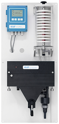
This method is unique in that it is an EPA-approved turbidity monitoring method for a non-contact turbidimeter 49. As a non-contact, or surface scatter, nephelometer, the AMI Turbiwell is intended for continuous monitoring, like other process or on-line monitoring instruments. Until 2009, no surface-scatter design was approved by the USEPA 16,41.
This design requires that the light source be an LED with a spectral response between 400 and 600 nm 48. The incident light beam should be angled to reach the water’s surface at a 45-degree angle, +/- 5 degrees. A beam splitter should be used to deflect a small portion of this light beam before it hits the water. This deflected beam is used a a reference signal to monitoring light intensity 48. The primary photodetector is set at a right angle to the light source, and should have a peak spectral response between 400-600 nm. An algorithm then determines turbidity levels based on the light intensity of the scattered and reference signals 48.
Though it is a surface-scatter design, the total distance traveled by the light beam (from the LED source to the photodetector) should not exceed 10 cm 48. To be approved by the EPA, this method can only be used for the range of 0-40 NTU. However, the nephelometer itself can be used up 200 NTU, though these readings will not be considered EPA-compliant 49.
Measuring Turbidity through Water Clarity Methods
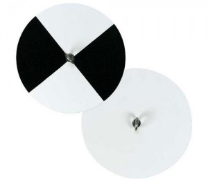
Water clarity and turbidity are directly related. In any body of water, the higher the turbidity, the lower the water clarity will be. However, while one is often an indicator of another, measurements between the two parameters are not interchangeable.
Water clarity is measured by a Secchi disk 7. Named after Angelo Secchi, these discs are usually quartered in black and white, though solid white and solid black discs are used in certain environments.
Secchi disks are used in lakes, oceans and deep rivers, where they are lowered into the body of water until they are no longer visible. Then they are slowly raised back to the last point of visibility, and that depth is recorded. The depth at which visibility is lost is known as the Secchi depth (7). High Secchi depths are associated with high water clarity and low turbidity, while low Secchi depths indicate high turbidity.
Secchi disk readings rely on light attenuation in water. In other words, they measure the depth of visibility based on light penetration 9. When the disk is underwater, light reflects off of it, making the disk visible to the human eye. When the disc is obscured by suspended sediment, algae or dissolved colored material, the light is no longer directly reflected back to the viewer 9. Instead, it is scattered and diffused. The more scattered the light becomes, the less visible the disc will be until it disappears completely.

Larger, solid white Secchi disks are commonly enlisted in marine environments, while the black and white quartered disc is the standard for lake studies. These discs are usually attached to a measuring tape or rod for ease of measurement. When using this method, readings are usually recorded in meters or centimeters, though some organizations use English units.
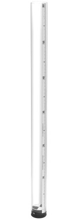
Solid black Secchi disks are useful in shallow lakes and rivers, where they are used to take horizontal measurements instead of vertical depths 13. This allows for a more accurate water clarity reading in shallow water bodies where a disc would still be visible on the bottom. The solid black disc provides greater visibility despite sunlight penetration, and a horizontal measurement offers the ability to take a Secchi reading that is greater than the depth of the water.
In shallow streams, where neither vertical nor horizontal methods are effective, a transparency or Secchi tube can be used 10. Transparency tubes can be found with the black/white disc permanently affixed to the bottom of the tube, or with the disc separate. In the first style, the transparency tube is slowly filled with water until the disc on the bottom disappears 2. The depth is then read from the side of the tube. In the second model, known as a standard Secchi tube, a one-meter-long tube is filled with water. The separate Secchi disc is then lowered into the tube until it is no longer visible. The point of disappearance is then recorded, just as it would be with a larger disc in a body of water 10.
While these water clarity methods have been used effectively, they are only as accurate as the user’s eyesight. Secchi readings can be affected by changes in sunlight conditions, choppy water, time of day, and human error in reading the Secchi depth. In addition, they are not practical when turbidity is below 5 NTU or if a high resolution is required. As the World Health Organization and other agencies specify a maximum of 1 NTU for drinking water, Secchi disks and tubes cannot be used to ensure compliance 8. However, they are affordable, portable and fairly intuitive to use. Secchi disks have been used for decades in places like Lake Tahoe, where more than 45 years of Secchi depth data can reveal trends in water clarity 12.
Historical Turbidity Measurement Method
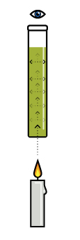
The historical method for measuring turbidity was the Jackson Candle Turbidimeter 31. Developed over a century ago, this instrument was constructed from a candle and a flat-bottomed glass tube. Much like a transparency tube, water is poured down into the tube until the candle flame is no longer distinctly visible 2. The light does not disappear completely, only the image of the flame will. This occurs when the intensity of the transmitted light is equal to the amount of light scattered by particles in the water 31. The more turbid the water is, the quicker the image of the flame disappears.
The Jackson Candle Turbidimeter was the first practical attempt to quantify turbidity. In addition to the instrument, a standard suspension was developed, allowing the tube to be “calibrated” to the user’s eye 31. While the scale of the turbidimeter was in ppm-silica, units for this instrument were called Jackson Turbidity Units (JTU). After formazin was invented in 1926, it was used as a new calibration standard for this method, and Formazin Turbidity Units (FTU) were adopted 31. However, even with the improvement in standards, this method was limited in scope. The Jackson Candle Turbidimeter could not detect turbidity levels below 25 JTU 2,31. It was also highly subjective as readings were based on human observation. This introduced errors based on personal perception and judgment 31. Other light-extinction based turbidimeters were developed, but they remained dependent on human eyesight 31. Today, these methods are considered obsolete in favor of turbidity instruments (such as meters and sensors) that offer an increased measurement range and improved accuracy 2.
Measuring Turbidity with a Turbidity Meter
One of the more common methods of measuring turbidity is with a turbidity meter. Turbidity meters can be handheld and field-ready or intended for laboratory benchtop use. These instruments use a light source and one or more detectors to measure the light scattered by particles in water samples 7.
Light Scatter
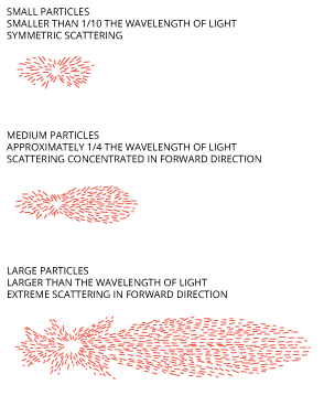
Light is scattered and absorbed by particles in the water 11. Even clear water will have minute light scatter due to the presence of dissolved particles and molecules 16. This scatter can be in any direction, and the intensity in any given direction is dependent on both the light source and the size of the particle(s). When a particle is much smaller than the beam of light, the scattering is fairly symmetrical in all directions 11. The larger the particle becomes, however, the more light that will be scattered forward (away from the light beam).
Wavelength also affects light scatter. In general, shorter wavelengths will scatter more than longer wavelengths for the same particle size 32. Shorter wavelengths are also more susceptible to absorption by colored molecules in the sample. Near-infrared light is rarely absorbed, so dissolved colored material will not affect it 32. This is one of the reasons that turbidity measurements made through different methods are often not comparable – if the light source is different, the light scatter will be different. While this is accounted for in the calculations, equivalent results are guaranteed.
The distance traveled by scattered light also affects turbidity readings. The longer the light path between the light source and the photodetector, the better the resolution of the instrument at low turbidity levels 16. The longest path lengths are at 90 and 180 degrees. However, increasing the path length sacrifices measurement range. Both the EPA 180.1 and the ISO 7027 methods limit light path length to 10 cm total 11. A decreased path length (such as a backscatter-based photodetector) increases the turbidity measurement’s upper limit 11.
However, the more particles present in the sample, the more the light will be scattered 16. Turbidity meters measure the amount of light scattered at a specific angle, and convert that reading into a turbidity measurement 16. Some turbidimeters are designed to compensate for color absorption and high turbidities, while others are intended for precise and accurate readings at very low turbidity levels. Most turbidity meters use nephelometric technology, though attenuation and ratiometric instruments exist.
Nephelometry
Nephelometry means that the light source and the photodetector are set at a 90-degree angle from each other. This is considered the angle most sensitive to light scatter regardless of particle size 29. However, it is limited to lower turbidity levels (below 40 NTU) and is susceptible to interference from dissolved colored material 16,24. Accurate nephelometric measurements are limited to 0-40 NTU due to the relationship between light scatter and turbidity. In this range, light scatter and turbidity have a linear relationship 32. This linearity is lost as turbidity levels rise above 40 NTU.

Despite these disadvantages, this technology is the most common used for turbidity detection angles and is the basis of many turbidity instrument designs 24. Nephelometric designs can be compliant with either EPA Method 180.1 or ISO 7027, depending on the light source used 16. If the light source is a tungsten filament lamp, the instrument is compliant with EPA Method 180.1 and Nephelometric Turbidity Units (NTU) should be used. ISO 7027 nephelometric instruments use a near-infrared LED light source, and Formazin Nephelometric Units (FNU) are recommended 18.
Nephelometric technology is based on the following algorithm:
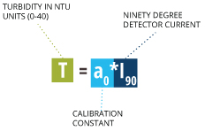
T = a0 * I90
T = Turbidity in NTU Units (0 – 40)
a0 = Calibration constant
I90 = Ninety degree detector current 11
As noted above, basic nephelometric designs are only recommended for use with turbidity samples between 0-40 NTU. At higher turbidities, light scatter can hit multiple particles as it travels, diminishing the light intensity 16. As the light intensity decreases, the accuracy of the instrument decreases. To compensate for this effect, a sample can be diluted to below 40 NTU. As both the EPA Method 180.1 and ISO 7027 allow sample dilutions, this can be used with higher turbidities per the chosen method’s recommendations 6. As it is susceptible to color interference and is not reliable at higher turbidities, many instruments have expanded upon this design. By combining nephelometric technology with an attenuation detector or an additional angled detector, the accuracy and sensitivity of the instrument can be improved 16.
Attenuation
Attenuation is the loss of intensity. In terms of turbidity measurements, attenuation refers to the loss of light between a light source and a detector directly across from it (180 degrees). This loss of light can be due to both scattering and absorption. Turbidity meters that rely on attenuation alone are the most susceptible to light absorption and color interferences 24.
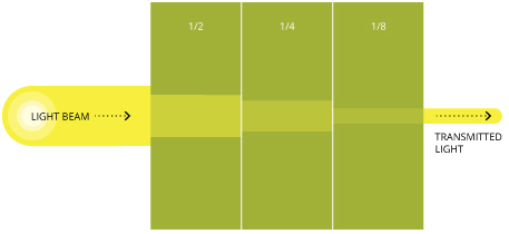
As attenuation designs do not actually measure scattered light, they are also known as transmittance turbidimeters, or absorptometers 16. They do not measure in true turbidity units. These instruments only measure the amount of light that is transmitted between the light source and the photodetector, and are reported as a percentage value of the original light amount 16. When in compliance with ISO 7027, turbidity levels must be over 40 NTU, and are reported in Formazin Attenuation Units (FAU) 39. Attenuation turbidity instruments are not approved by the EPA, though they can be used to approximate water cleanliness.
This is the technology used in colorimetry instruments, where the interference from color is expected and intended as part of the measurement. These instruments assume that the molecules are uniformly distributed throughout the sample 38. Color and turbidity are related, as color molecules absorb light, affecting the clarity of the water 18. However, turbidity measurements based on dissolved colored material do not correlate in any way with suspended sediment concentrations or total suspended solids. As colored samples do not necessarily contain sediment or solids, they will not affect those concentrations. Colorimetry measurements can be calculated by the following formulas 38:
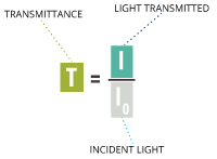
T = I / I0
T = Transmittance
I = Light Transmitted (received)
I0= Incident Light (initial)
A = Log(1 / T) = a * b * c
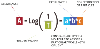
A = Absorbance
T= Transmittance
a = Constant, ability of a molecule to absorb a particular wavelength of light
b = Path length
c = Concentration of particles
Ratio Designs (Nephelometric)
When used in correlation with nephelometry and other angles, attenuation-angled photodetectors can assist in improving turbidity meter accuracy 11. This is often referred to as a ratio design. Ratio, or ratiometric turbidity meters are still categorized under nephelometric technology as a 90-degree angle is used as the primary detector. With multiple photodetector angles, algorithms may be used to compensate for optical interferences and increase instrument sensitivity 16,24. The Standard Methods ratiometric method uses the following algorithm:
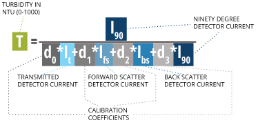
T= I90 / (d0 * It + d1 * Ifs + d2 * Ibs + d3 * I90)
T = Turbidity in NTU (0-10000)
d0, d1, d2, d3 = Calibration Coefficients
I90 = 90 Degree Detector Current
It = Transmitted Detector Current
Ifs = Forward Scatter Detector Current
Ibs = Back Scatter Detector Current 11,16
The use of multiple detectors can improve accuracy and decrease the interference from dissolved colored materials and stray light. This is most obvious between the nephelometric (90-degree) and attenuated or transmitted, (180-degree) detectors. As the light beam travels nearly the same distance to either of these photodetectors, the effects of color in the water sample will cancel mathematically 11,16.
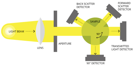
While they are not very sensitive on their own, forward-scatter detectors offer a linear response over a wide turbidity range 11. When used in conjunction with nephelometric and other angles, the forward-scatter detectors can increase range and resolution while reducing error from color and electronic noise 11. Backscatter detectors are typically only necessary in very high turbidity applications (over 4000 NTU), though they are frequently used in applications over 1000 NTU 32. At these levels, backscatter detectors receive more scattered light than the other angled detectors and reflect a linear response 11. At levels below 1000 NTU, backscatter detectors may begin to interfere with the turbidity measurement instead of improving it. As backscatter levels are extremely low below 1000 NTU, the detector will produce more electronic noise than measured signal 11. Improved detector materials can reduce instrument noise.
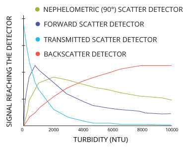
As long as one of the photodetectors is at a 90-degree angle, ratio designs can be compliant with EPA Method 180.1 or ISO 7027 11. The instrument will still need to be in agreement with the light source, light travel distance and other requirements of the chosen method. The presence of additional photodetectors does not change compliance. However, it is recommended to use units which indicate the use of multiple detectors. For EPA Method 180.1 ratiometric designs, the USGS recommended unit is the Nephelometric Turbidity Ratio Unit (NTRU), while ISO 7027 compliant ratio designs should use the Formazin Nephelometric Ratio Unit (FNRU) 18.
GLI2 compliant instruments are examples of multi-beam ratiometric designs. These instruments use two light beams in addition to two detectors, greatly improving the sensitivity and accuracy of the instrument 16. These instruments should use Nephelometric Turbidity Multibeam Units (NTMU) or Formazin Nephelometric Multibeam Units (FNMU) depending on the light source.
Measuring Turbidity with a Turbidity Sensor
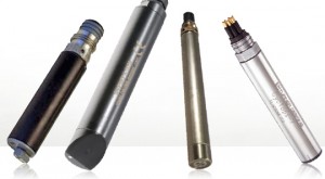
Use of a dynamic turbidity instrument, or turbidity sensor, is becoming more and more popular for use in water quality monitoring. Turbidity sensors are also known as submersible turbidimeters 28. Dynamic measuring means that a turbidity sensor is submerged in a body of water, taking measurements under natural conditions 18. Static measurements, on the other hand, are based on samples that have been removed from the water source. As such, turbidity sensors are ideal for use in streams, rivers, lakes and oceans, due to their monitoring of current, in-situ conditions. The ability to submerge a sensor directly in a body of water also offers the option of relatively continuous monitoring in addition to taking an instantaneous reading 51. A submerged turbidity sensor can be deployed, or left unattended, for relatively continuous surface-water monitoring.
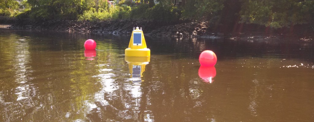
According to the United States Geological Survey, dynamic (in-situ) measurement with a turbidity sensor is the preferred method for turbidity monitoring 18. In addition to their ability to provide continuous turbidity data, in-situ measurements are considered more credible than sampling methods in terms of surface-water conditions 18. Dynamic instruments can more accurately reflect particle movement in the water, particularly when larger sediment is present. These sensors are also helpful in dredging applications, when it is necessary to watch ambient turbidity levels for increases above accepted limits 51. Furthermore, with a turbidity sensor, there is no risk of errors due to unrepresentative subsampling, artificial settling, or other introduced interferences (e.g. a scratch on the glass) as there would be in a sample cell 18.
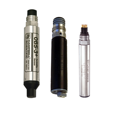
Like most lab and process instruments, many turbidity sensors use nephelometric technology. However, other design models, such as backscatter instruments, are also used. In addition, not all nephelometric turbidity sensors are compliant with water quality monitoring design standards. This simply means that while these instruments can still be used, data are not inter-comparable and care should be taken to use ASTM/USGS recommended units 51. The lack of compliance in turbidity sensors is not indicative of accuracy, but only that an instrument does not meet every single requirement of a design standard. These instruments can still be used to effectively monitor changes in turbidity as long as the appropriate units are used. Unless a sensor uses a white light (400-680 nm) LED with a single nephelometric photodetector, NTU should not be used 18. Most turbidity sensors on the market today use an infrared light source and will use either FNU or FBU as the recommended turbidity unit 50.
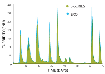
With turbidity sensors, just as with turbidity meters, it is important to use the same instrument throughout a study for internally consistent data 51. The use of recommended units will also ensure accurate results, as turbidity units on their own have no inherent value 52. Data from different instrument designs are not comparable as each sensor will read light scatter from suspended particles differently, outputting different measurements for the same water sample 51. Some sensors are more accurate at low turbidity levels, while others offer the ability to measure a wide turbidity range. Only sensors that comply with the same design standard and measurement method have comparable data, and even then there are differences at high turbidities, as seen in the graph on the left. ISO 7027 compliant turbidity sensors are only comparable between 0-40 NTU. Outside of this range, it is recommended to only compare data from the same sensor model.
Nephelometric Turbidity Sensors
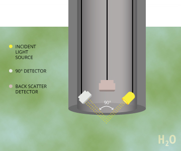
As of 2013, there are no true, EPA 180.1 compliant, dynamic turbidity sensors on the market 50. The requirement of a tungsten lamp light source makes any such instrumentation impractical due to the high power draw and the instability of the light source 51. LED light sources on the other hand are compact with a small power draw. In addition, LEDs have a longer lifetime, no warm-up period, and can be modulated to reject ambient light 51,60. As such, most submersible turbidity sensors use at least one LED light source. Of those, several are ISO 7027 compliant sensors, though other nephelometry-based sensors exist and can be used to measure turbidity in surface waters.
Many turbidity sensors imply compliance with either EPA or ISO standards because they utilize nephelometric technology. However, if they do not meet other specifications in the design standard (such as the use of a tungsten lamp, or a limited photodetector angle of 90 +/- 2.5 degrees), then the instrument is not 100% compliant 51. Instead, it is only based on a particular standard. Turbidity sensors that do not comply with a design standard can still be used to measure turbidity, but their data cannot be compared to data from other instruments. As such, it is important to use the recommended turbidity units for each sensor based on their design.
Most nephelometric turbidity sensors follow ISO 7027 guidelines. While any design could be used, compliance with ISO 7027 ensures accurate, comparable turbidity data. Just as with turbidity meters, sensors with an infrared light source will have minimal color interference 60. In addition, the use of a compact, low-power LED light source is ideal for long-term deployments with minimal servicing 51. The light source and the photodetector are located below two optical windows, and are tilted to achieve a 90-degree, scattered-light angle. To remain in compliance with ISO 7027, the optical windows must be narrow enough to maintain an acceptance angle of no more than 30 degrees 51. The two optical windows are generally located on the same flat surface of the sensor. This means that these sensors can also be built with a programmed wiper to prevent fouling (attachment of biological material such as algae or barnacles). The flat optical surface can be wiped by an attached brush, keeping the turbidity sensor clean for long deployments in the ocean or biologically-active surface-water 51.
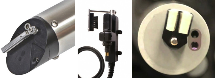
If an EPA approved method is required, there are submersible turbidimeters in compliance with GLI Method 2. Submersible turbidimeters in compliance with EPA-approved Orion Method AQ4500 may also be possible, as the design requirements of this method can be adapted to a sensor body. GLI2 turbidity sensors have a doughnut-shaped sensor body, with four optical windows located on the interior at 90 degrees from one another 37. With two infrared LED light sources, and two nephelometric photodetectors (alternating nephelometric and transmittance detection), GLI Method 2 turbidity sensors are also compliant with ISO 7027 37. However, sensors with a GLI Method 2 design are limited in range and environmental use 51. These turbidity sensors cannot be remotely wiped, which means they risk fouling and thus inaccuracy in biologically active water.
Turbidity and Temperature Compensation
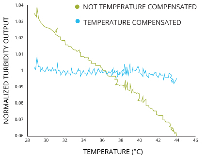
Turbidity itself is not affected by temperature. However, when using a submersible turbidity sensor with an LED light source, data should be temperature compensated. This is due to the effect that the changes in temperature have on the electrical output of the sensor 61. Fluctuations in temperature will alter turbidity readings even though actual turbidity levels remain the same 61.
The need for temperature compensation is due to the relationship between optical power output and environmental temperature 62. As temperature increases, output (brightness) will decrease. This in turn affects the measured turbidity reading, as less light intensity reaches the photodetector, so an erroneous, smaller turbidity level is read.
In most applications, water temperature will not fluctuate enough to significantly affect readings. To ensure accurate measurements, however, it is necessary to account for any minor changes 61. This is especially true if an LED light source is used. LEDs heat up as they are used, and are thus a source of temperature fluctuation 61. In most source-water applications, the LED is the main culprit in localized temperature changes 63. As the LED heats up, the intensity of its output will decrease. The radiation intensity of the LED is proportional to the logarithm of the ambient temperature, which means that linear equations can be used to compensate for temperature 61,62. Some turbidity sensors will include a built-in thermistor to compensate for the effects of temperature directly at the source 63. Others sensors offer the ability to make these adjustments in their software 59. For sensors without the ability to compensate for temperature, a drift will be noticeable in the turbidity readings as the LED heats up.
Backscatter Turbidity Sensors
A backscatter turbidity sensor uses a light source and a photodetector set past the 90-degree angle. While no current design standard exists for these sensors, the USGS and various manufacturers have attempted to define acceptable backscatter angles 50. The USGS suggests that any turbidity sensor with a 0-45 degree detection angle (135-180 degrees from the transmitted light) is considered a backscatter instrument 24,50. However, as there is no standardized backscatter method, any scattered light detection beyond the nephelometric 90-degree angle can be accepted as a backscatter sensor 51,52. A study by Boss and Pegau recommends using a detector at a 63-degree angle (117-degree angle from the transmitted light) 53. This angle is a minimum convergence point, which means that the turbidity reading is a more accurate representation of concentration and less affected by the size and color of suspended particles 53.
Instruments with any backscatter detection angle are further divided by their light source: white/broadband or near-infrared. Turbidity sensors with a backscatter detector and a light source with a wavelength between 400-680 nm should use Backscatter Units (BU), while those with a 780-900 nm wavelength should use Formazin Backscatter Units (FBU) 50. Most backscatter sensors use an LED or a laser diode as their light source. Due to the proximity of the detector and the diode, backscatter instruments are usually constructed with a light baffle or other separator to prevent the photodetector from receiving light directly from the source 52.
The advantage of backscatter turbidity sensors is the wide measurement range and the improved accuracy at higher turbidities and the tolerance of a range of particle sizes 11,51. Between 1000-4000 NTU, backscatter technology is nearly perfectly linear 11,51. In low turbidity applications however, a backscatter instrument will not be as accurate as a nephelometric sensor 18,24. Backscatter sensors are also more sensitive to color interference based on particle darkness value (ability to reflect near-IR bands) 51. These instruments are often used in applications that require wide-range turbidity monitoring, particularly when there is a possibility of turbidity spikes.

Attenuation Turbidity Sensor
Light attenuation is also known as transmittance, and it measures the amount that light intensity decreases. This is the technology that is often used in smart washing machines and dishwashers 36. These turbidity sensors measure the amount of soiling in the water. The amount of light that reaches the photodetector will determine how long to wash in each cycle, conserving energy when little to no turbidity is present 36. The decrease in light intensity can be due to absorption (color) or scattering (particles). Due to the strong susceptibility to color interferences, attenuation turbidity sensors are not recommended for use in surface-water quality measurements.
Total Suspended Solids Measurement Methods
Due to the correlations between turbidity and total suspended solids (TSS), turbidity measurements are often substituted for suspended sediment concentrations and TSS measurements 24. However, when possible, it is more accurate to measure total suspended solids by weight 25. Turbidity readings can be affected by colored dissolved organic matter (CDOM), while sediment and TSS measurements are not. While the most accurate and accepted method for measuring suspended sediment and TSS is by weighing a sample, the USGS has begun using acoustic Dopplers for in-situ sediment monitoring 4.
Total Suspended Solids and Suspended Sediment Concentration by Weight
Measured in milligrams per liter of water (mg/L), suspended sediment concentration and total suspended solids readings are based on filtered and dried water samples. TSS encompasses any particles larger than 2 microns in diameter. Any particle smaller than this is considered a dissolved solid 3.

The main difference between total suspended solids (TSS) and suspended sediment concentration (SSC) is in the amount of water analyzed 26. After filtering a water sample with a 2-micron filter, the particles are dried and weighed to determine suspended solids. When an entire sample is filtered, dried and weighed, the American Society for Testing of Materials considers the measurement to be the suspended sediment concentration 27. If a water sample is further subsampled, the subsequent mass measurement will be the TSS measurement 26. This can be done by shaking/stirring and pouring from the sample bottle (EPA method) or by stirring and collecting a sample with a pipette (APHA method) 27. The EPA method is considered more consistent than the pipette method 25,27.
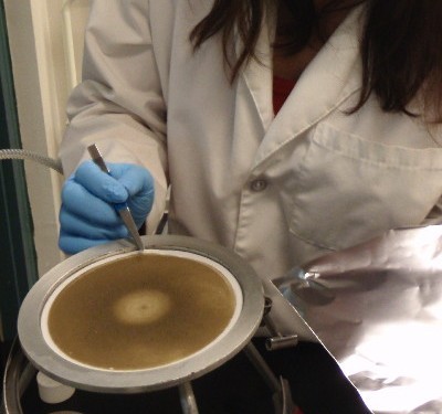
For samples with fine suspended particles (less than 53 microns), the total suspended solids measurement and the suspended sediment concentration will be both precise and accurate relative to the true concentration and each other 27. However, if larger (medium-coarse) particles are included in the sample, sub-sampling can often introduce error into the TSS measurement. The larger the particle, the more likely that it will not be included in the sub-sample. Coarse sediment, such as sand, is often not included in the TSS measurement 26. This is due to the rapid settling of larger particles. On the other hand, regardless of particle size, the SSC is usually within 5% of the true particle concentration 27.
Total Suspended Sediment by Acoustic Doppler Measurements
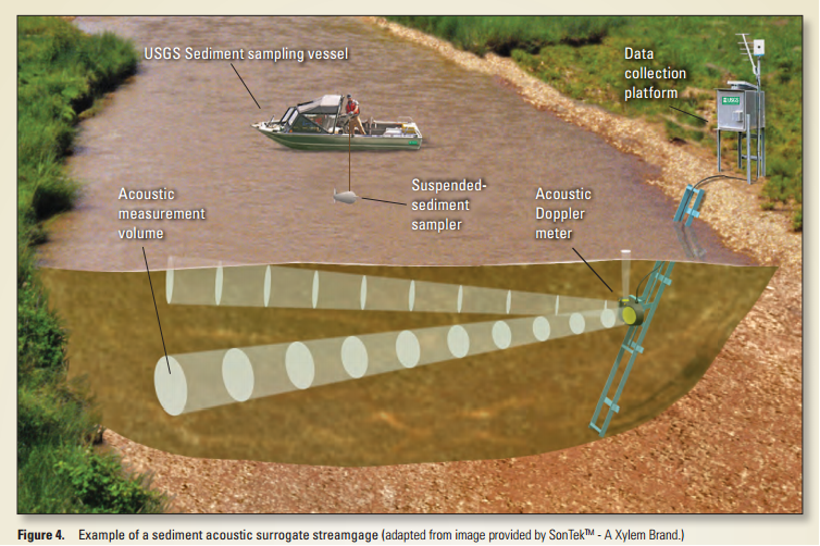
The U.S. Geological Survey has started using acoustic Doppler meters to determine continuous sediment loads estimates 4. As the Doppler meter pulses sound through the water, the frequency beams will bounce off suspended particles in the water. While these meters are generally used to measure water velocity, the returned beams, known as backscatter, can be used to indicate suspended sediment concentrations 4. This method requires correction for any sound absorption and beam spread. While it is not as accurate as a TSS mass measurement, and while its performance is still under study, the use of an acoustic Doppler meter opens the door to the possibility of continuous suspended sediment estimates 4.
Measurement Comparison
When monitoring drinking water in the U.S., compliance with one of the eight EPA-approved methods is required 18. However, it is important to remember that data from different instruments are not comparable, even if they are calibrated with the same standard 11. Across methods, the differences in light sources play the biggest role in non-comparability, though photodetector material and instrument design in general also play a role 11,16. Suspended particles will scatter long and short wavelengths differently, so infrared and white light sources are not directly comparable 28. Furthermore, the use of color-compensating ratiometric designs will also alter the turbidity measurement. While the variety of methods and designs allow a turbidity sensor or meter to be chosen for a specific application, it also limits data comparison 18.
Simply because an instrument will provide several different unit output options does not mean that the results are accurate or comparable. Turbidity units have no intrinsic value 52. Their accuracy and usefulness is defined by the instrument design and measurement method. This is why it is extremely important to use the recommended units based on the turbidity sensor or meter design.
Cite This Work
Fondriest Environmental, Inc. “Measuring Turbidity, TSS, and Water Clarity.” Fundamentals of Environmental Measurements. 5 Sep. 2014. Web. < https://www.fondriest.com/environmental-measurements/measurements/measuring-water-quality/turbidity-sensors-meters-and-methods/>.


