
Cause and Effect Diagram (aka Ishikawa, Fishbone)
A Cause and Effect Diagram (aka Ishikawa, Fishbone) is a picture diagram showing possible causes (process inputs) for a given effect (process outputs). In other words, it is a visual representation used to determine the cause(s) of a specific problem.
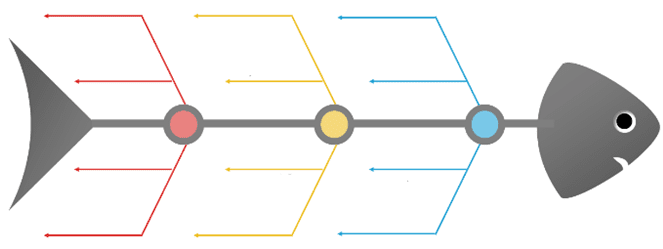
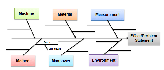
The Cause and Effect diagram is called the “Ishikawa diagram” or fishbone diagram. This is because the diagram looks much like the skeleton of a fish. Fishbones are drawn right to the left, with each large bone of the fish drawn out to include smaller bones that add more detail.
The Cause and Effect Diagram (aka Ishikawa, Fishbone) introduced by Kaoru Ishikawa (1968) shows the causes of a specific event. Additionally, Ishikawa introduced the company-wide quality control (CWQC) and the Quality circles concept in Japan. Common uses of the Ishikawa diagram are product design and quality defect prevention to identify potential factors causing an overall effect. It is one of the seven basic tools of quality control.
In particular, this method is common in brainstorming and in the “open” phase of root cause analysis.
Mục lục
When to use the Cause and Effect Diagram
- When the problem has multiple possible causes
- To identify the possible root causes for an effect
- Identify and sort interactions among the factors on an effect
- Finally, to initiate appropriate corrective action for existing problems
Why use Cause and Effect Diagram
- It is a basic step to study a problem and determine the root cause.
- It allows you to study all the probable causes of why a process begins to have a problem.
- It helps you identify areas of data collection for further study.
How to develop a Cause and Effect Diagram
The Cause and effect diagram is a structured graphical diagram listing all possible causes and their relationship with the main effect or problem. The diagram’s basic input is the brainstorming that pushes to identify all the possible causes rather than just more noticeable ones.
Following are the steps to draw a fishbone diagram:
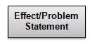
Step 1: Identify the problem:
- Firstly, identify and clearly write down the effect or a problem that needs to be analyzed
- Then create an operational definition of a problem to ensure all the stakeholders will understand it
- An effect may be positive, like an objective (to improve the process further), or negative, like a problem (to identify customer dissatisfaction).
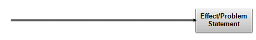
Step 2: Determine Effect or Problem:
- Next, draw a horizontal line. This is a spine
- At the end of the spine, towards the right, draw a box and determine the description of an effect
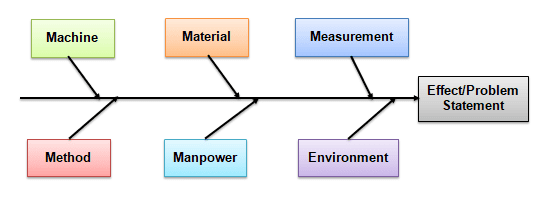
Step 3: Identify major causes contributing to the effect or a problem
- Establish main causes and write down a few main causes above the horizontal line and a few below the horizontal line. Make sure they are placed on the tail of the same arrows.
- Each cause or reason for imperfection is a source of variation. Causes are usually grouped into major categories to identify these sources of variation. These include: (Also see the 5Ms and 1P).
- Man/People: Anyone involved with the process.
- Methods: How the process is performed and the specific requirements for doing it, such as policies, procedures, rules, regulations, and laws.
- Machines: Any equipment, computers, tools, etc., required to accomplish the job.
- Materials: Raw materials, parts, pens, paper, etc., used to produce the final product.
- Measurements: Data generated from the process that is used to evaluate its quality.
- Environment: The conditions, such as location, time, temperature, and culture, in which the process operates.
Step 4: Identify sub causes
- Identify as many sub-causes that are relevant to the main causes and are placed under each main cause category.
- For instance, if the sub-cause applies in multiple places, list it under each main category.
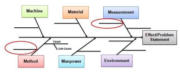
Step 5: Analyze the diagram
- At this time, the fishbone diagram shows all the possible causes of an effect.
- Identify causes that are not impacting the effect and also identify causes that need further investigation.
- Further, perform a 5Why analysis of the identified causes (also called noises) to arrive actual root cause.
Cause and Effect Diagram Example
By and large, Fishbone diagrams are used to identify the root causes of a problem in the “Analyze” phase of Six Sigma’s DMAIC (Define, Measure, Analyze, Improve, and Control).
Example: XYZ is a valve manufacturing unit receiving persistent customer complaints about the valve diameter. The plant’s General Manager asked QA and Production team to conduct a root cause analysis. So, the team performed Brainstorming and drew the Cause and Effect diagram to identify all the possible causes.
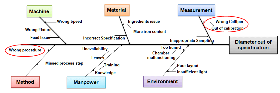
The team identified that the wrong caliper and wrong procedures were the probable causes. Further, the team has to perform a 5 Why analysis to identify the root cause.
Benefits of Cause and Effect Diagram
- Helps to identify all the probable causes of an effect to identify root causes further.
- Further, it graphically displays all the possible causes related to a problem to discover the root causes.
- Fosters teamwork and inspires the team to brainstorm until the elimination of the root cause.
- Easy to implement in any case.
- A common understanding of the factors causing the problem.
- Establish brainstorming relationship.
Fishbone Diagram Best Practices
- Focus on the cause, not just solutions.
- Go beyond the superficial levels to find root causes. So, don’t merely outline options.
- Finally, ask “why” until it is absurd to continue.
Cause and Effect Diagram Template Download
Unlock Additional Members-only Content!
To unlock additional content, please upgrade now to a full membership.
Upgrade to a Full Membership
If you are a member,
To unlock additional content, please upgrade now to a full membership.If you are a member, you can log in here.
Fishbone Diagram videos
Further, Minitab put out a good video on how to use their software to brainstorm and create a fishbone diagram. If you’ve never done this before, this is a great reference.
ASQ Six Sigma Black Belt Exam Fishbone Diagram Questions
(Taken from ASQ sample Black Belt exam.)
Question: A company’s accounts payable department is trying to reduce the time between receipt and payment of invoices. If the team has just completed a process flow chart and identified the critical steps, which of the following tools should be used next?
A) Fishbone diagram
B) Scatter diagram
C) Box and whisker plot
D) Histogram
Answer:
Unlock Additional Members-only Content!
To unlock additional content, please upgrade now to a full membership.
Upgrade to a Full Membership
If you are a member,
To unlock additional content, please upgrade now to a full membership.If you are a member, you can log in here.
Authors
Ted Hessing
Ramana PV