
Cause and Effect Diagram (Fish Bone) – Quality Improvement – East London NHS Foundation Trust
Mục lục
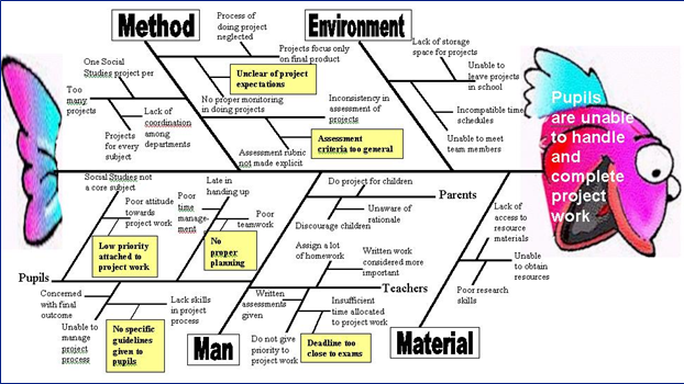
Cause and Effect Diagram (Fish Bone)
What is it and how can it help me?
Cause and effect analysis helps you to think through the causes of a problem thoroughly, including its possible root causes. It is only by identifying the main causes that you can permanently remove the problem, or reduce the delay.
A cause and effect diagram is a tool that helps you do this. The ‘effect’ is the problem you are working on, for example ‘waiting time’. The tool can help you identify major causes and indicate the most fruitful areas for further investigation. It will help you understand the problem more clearly.
By going through the process of building the diagram with colleagues, everybody gains insights into the problem, alongside possible solutions. The people involved benefit from shared contributions, leading to a common understanding of the problem.
The cause and effect diagram is sometimes called a fishbone diagram (because the diagram looks like the skeleton of a fish) or an Ishikawa diagram (after its inventor, Professor Kaoru Ishikawa of Tokyo University).
When does it work best?
The tool quickly helps you to fully understand an issue and to identify all the possible causes – not just the obvious. If you know the cause of the delay, you are then better placed to implement the solution.
- What does it do?
Enables a team to focus on the content of the problem rather than its history or the differing interests of team members - Creates a snapshot of the collective knowledge and consensus of a team around a problem
- Focuses the team on the root cause of the problem – not its symptoms
How to use it
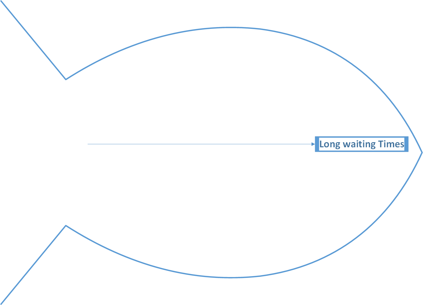
Firstly, identify the problem. Write it in a box and draw an arrow pointing towards it. Think about the exact problem in detail. Where appropriate, identify who is involved, what the problem is, and when and where it occurs.
Example:
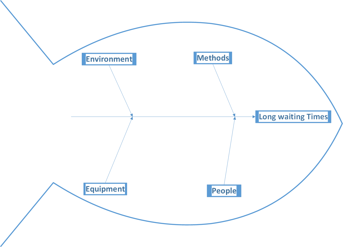
Identify the major factors and draw four or more branches off the large arrow to represent main categories of potential causes. Categories could include: equipment, environment, procedures, and people. Make sure that the categories you use are relevant to your particular problem / delay. An alternative way of creating the branches of a cause and effect diagram is to carry out the Affinity Diagram technique and use the group headings produced there.
For Example:
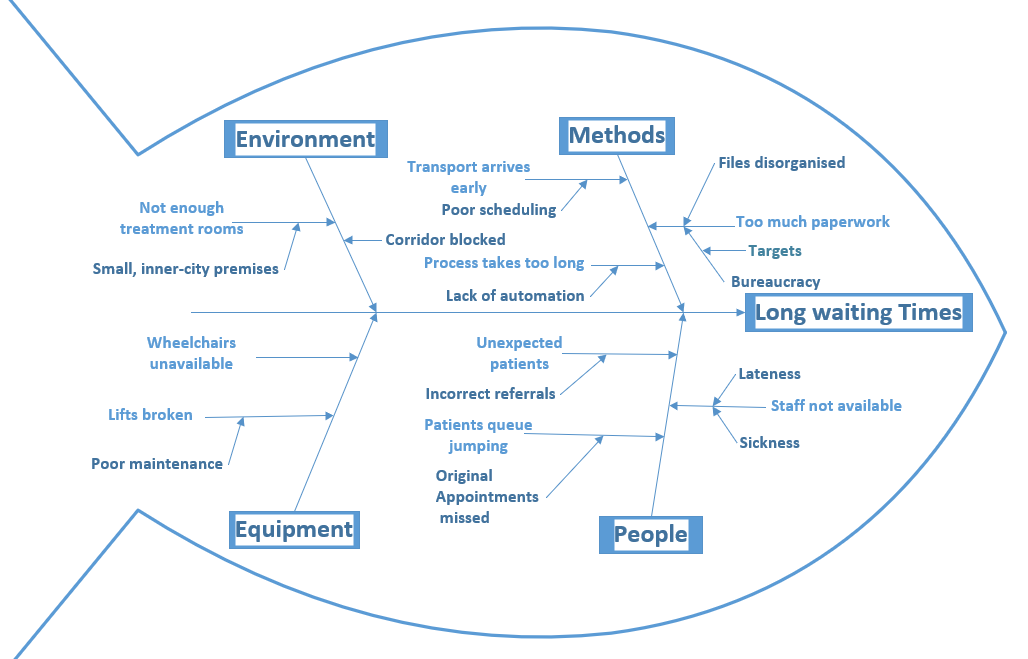
- Take each of the main categories and brainstorm possible causes of the problem. Then, explore each one to identify more specific ’causes of causes’. Continue branching off until every possible cause has been identified. Where a cause is complex, you might break it down into sub-causes. Show these as lines coming off each cause line.
- Analyse your diagram. By this stage you should have a diagram showing all the possible causes of your delay / problem. Depending on the complexity and importance of the problem, you can now investigate the most likely causes further. This may involve setting up interviews (see getting patient perspectives), carrying out process mapping or surveys which you can use to decide whether the causes identified are correct.
Tips:
- Make sure that your team agree on the problem statement. Include as much information as possible in the ‘what’, ‘where’, ‘when’ and ‘how much’ of the problem. Use data to specify the problem if possible
- Aim to construct the diagram with the people involved in the problem
- You can use a cause and effect diagram as a working document that is updated as and when you collect more data, or to trial various solutions
- Use a paper surface so that you can transport the final diagram
- Ideally, causes should appear in only one category, although some people causes may overlap
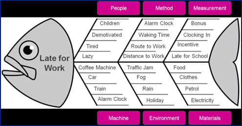
More examples
Background
The cause and effect diagram was adopted by Dr W Edwards Deming as a helpful tool for improving quality. Dr Deming has been teaching total quality management in Japan since World War II. He has also helped develop statistical tools used for the census, and has taught methods of quality management to the military. Both Ishikawa and Deming use this diagram as one the first tools in the quality management process.
Acknowledgements / sources
TIN, now the East Midlands Improvement Network and Dave Young.
© Copyright NHS Institute for Innovation and Improvement 2008
Found this page useful?
Sign up to the ELFT QI Newsletter to get QI news, stories and updates straight to your inbox