How To Use Control Charts To Improve Manufacturing Quality – dataPARC
Once a manufacturing process has been centerlined and is running relatively well, it is time to take the next step – measuring and tracking important product characteristics. One method of tracking involves the use of process control charts.
The main purpose of control charts is to help determine if a process is stable and in-control, or unstable and out-of-control. When a process is stable, or “in control,” this means that it is predictable and affected only by normal random causes of variation. An unstable or “out-of-control” process is affected by the same common causes of variation, but it is also affected by “special” or “assignable” causes. If you are successfully centerlining all important process variables, and your incoming raw materials are relatively consistent, then your process should be stable and in control.
Mục lục
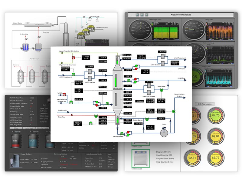
Real-time manufacturing operations management and industrial analytics tools
Check out PARCview
Control Chart Basics
A control chart consists of a time trend of an important quantifiable product characteristic. In addition to individual data points for the characteristic, it also contains three lines that are calculated from historical data when the process was “in control”: the line at the center corresponds to the mean average for the data, and the other two lines (the upper control limit and lower control limit) represent the average value plus and minus 3-sigma, where sigma is equal to the standard deviation.
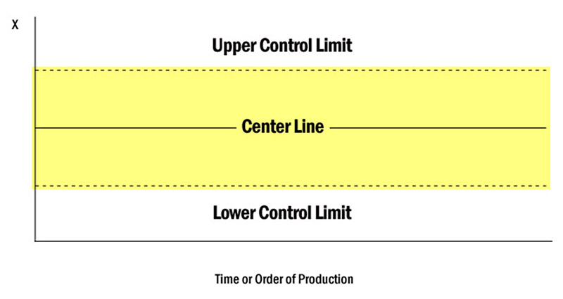
The standard deviation or sigma indicates how widely the data are dispersed or scattered around their mean average value. It was determined by Walter A. Shewhart that when a process is stable and in-control, over 99% of process values should fall between the 3-sigma control limits. If a value were to fall outside of these limits, this would indicate the presence of an unusual or special cause, and a process adjustment or corrective action would be in order. A special cause would also be indicated if the data were to exhibit some other non-random pattern, including an upwards or downwards trend, or a cyclical pattern.
Several different “rules” have been developed to determine when a process is “out-of-control” and a special cause is present. These are sometimes called the “Western Electric Rules” because they were first developed by Shewhart while he was working at the Western Electric Company.
A Clear Example
To better understand how control charts work, let’s go back to the coffee-making example from our post on Centerlining and imagine that coffee strength was being evaluated on a scale of 1 to 10 each time a new pot was made. The results were then plotted on a control chart, like this:
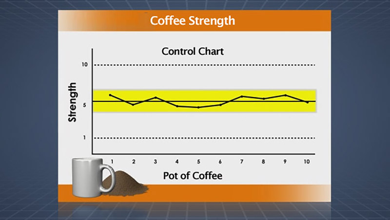
Recall that the horizontal center line represents the mean average value of recent coffee strength numbers, and the upper and lower lines represent the upper and lower control limits. If the coffee making process is stable and only affected by “common causes” of variation, virtually all coffee strength values should land inside the two control limits, scattered randomly above and below the average value.
If the coffee strength were to fall below the lower control limit or above the upper control limit, or if coffee strength were trending upward or downward, this would indicate a “special cause” and a process adjustment or corrective action would be called for.
On the road to digital transformation? Get our Free Digital Transformation Roadmap, a step-by-step guide to achieving data-driven excellence in manufacturing.
Using Control Charts In Manufacturing Processes
Used effectively, control charts are as much about minimizing the number of changes to the process as they are about making process changes. Let’s look at a couple of ways control charts can help maintain process integrity:
Real-Time Process Monitoring
In real-time, effective control charts should clearly communicate to the plant operator when the process has deviated outside of control, prompting the operator to make changes to the process.
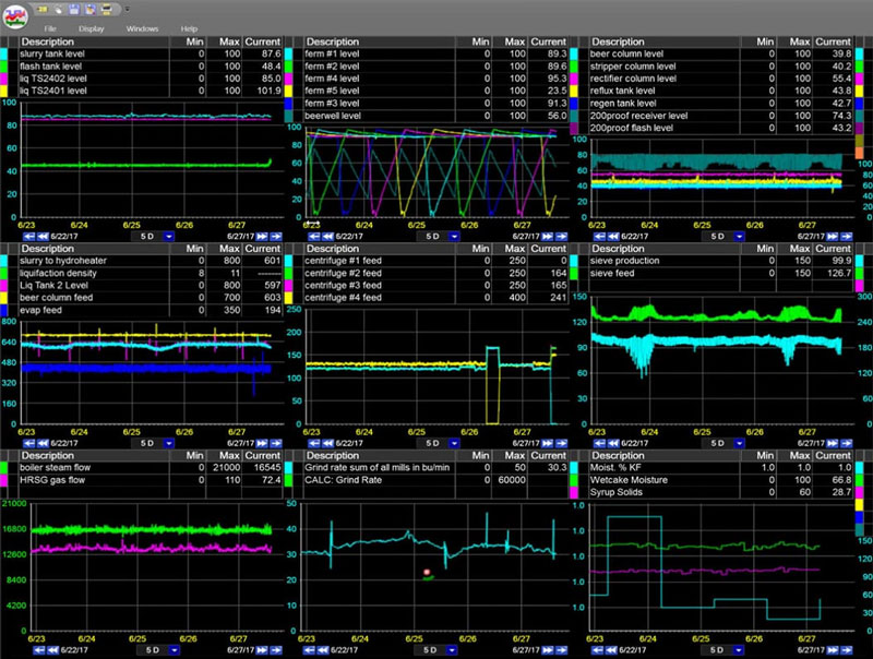
Use your facility’s Plant Information Management System (PIMS) or data visualization software to set up visual time trends that include averages and data limits. Configure alarms or alerts to be triggered when a tag value falls outside of the control limits, or when the presence of a “special cause” is indicated by one of the other Western Electric rules.
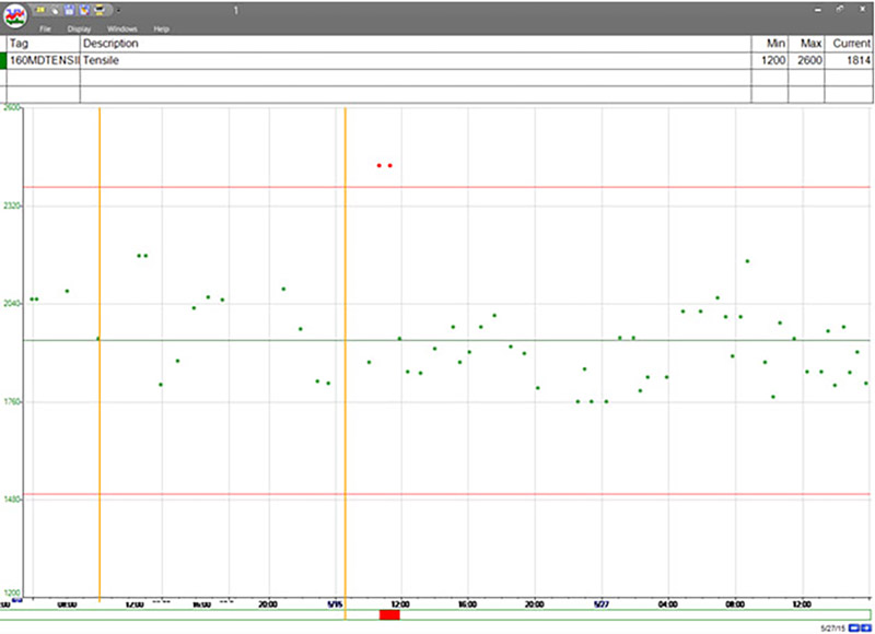
Check out our real-time process analytics tools & see how better data can lead to better decisions.
Check out PARCview
Root Cause Analysis
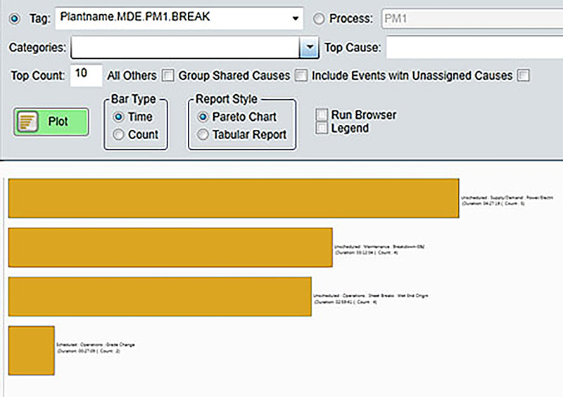
Another key function of effective Control charts is the facilitation of root-cause analysis initiatives. Many PIMS and software, such as dataPARC’s PARCview application, allow users to assign standardized reasons and add comments for out of control events. The events can then be used for analysis using Pareto Charts and KPI reports to identify the low hanging fruit and improve the process.
To learn more about how dataPARC and its applications – including PARCalarm and PARCpde – can be used to automatically calculate grade-specific or product-specific control limits for process tags and make those limits available throughout the system, please visit us at dataparc.com.
OEE: The Complete Guide
All the resources you need to successfully implement, analyze, & improve overall equipment effectiveness.
Get the Guide


