
Quality by Design and 9 Such Tools – Pharma GxP
Apart from process validation, pharma industries use several tools to improve their existing processes and verify their cleaning efforts.
In this post, I’ll be exactly sharing the glimpse of these tools that will help in process monitoring and optimization. Ultimately, will improve the productivity.
List of the tools to enhance your manufacturing, process validation, and cleaning validation efforts:
- Quality by Design
- Design of Experiments (DOE)
- Process Analytical Technology (PAT)
- Lean and Six Sigma
- pFMEA
- Process Capability
- 5 Why Analysis
- Fault Tree Analysis
- Fish Bone Diagram / Ishikawa Diagram / Cause and Effect Diagram
- Gage R&R Study
Under Quality by Design (QbD) approach, the FDA too encourages using these tools as risk reduction methods right from the process development till the commercial manufacturing.
1. Quality by Design (QbD)
A constant challenge for drug manufacturers is to create robust and high-quality processes. Reason being reduced productivity due to process variations.
In the past, testing and inspection were done to ensure quality, but control was the greatest concern.
In the same way as statistical approaches, Quality by Design is a scientific approach to reduce process variation and increase productivity.
Quality by Design overcomes such challenges with a distinct approach i.e., building the quality in the product right from the process design stage.
QbD calculates the extent of process variation by gathering all the CTQs and CPPs for the products in scope.
What is Quality by Design (QbD)?
A concept that quality should be built into a product with a thorough understanding of the product and process by which it is developed and manufactured along with a knowledge of the risks involved in the manufacturing of the product and how to best mitigate those risks.
Pharmaceutical Quality for the 21st Century A Risk Based Approach Progress Report Department of Health and Human Services U.S. Food and Drug Administration May 2007
Before moving ahead, let’s see some common terms used in the QbD.
Critical Quality Attributes (CQAs)
Critical Quality Attributes (CQA) OR Critical to Quality (CTQ) are the chemical, physical, and biological properties that shall be within appropriate limits to meet desired product quality and performance.
For example, the drying process has CQAs like:
- Bulk density
- Moisture content
- Product uniformity etc.
As its name suggests, these can be detrimental to product quality if not maintained.
Critical Process Parameters (CPPs)
The parameters whose variability affects the CQAs and hence must be monitored and controlled to ensure the desired product quality and performance are called Critical Process Parameters.
For example, the drying process has CPPs like:
- Drying time
- Airflow
- Temperature etc.
These CPPs directly or indirectly impact CQAs thereby affecting the product quality.
Quality Target Product Profile (QTPP)
Quality Target Product Profile (QTTP) is a synopsis for drug product qualities to be achieved at the final stage.
Cause and Effect Analysis (C&E)
Tool to investigate the cause and effect relationship for a failed process or product. This is explained through Fishbone or Ishikawa diagram further.
How Quality by Design Covers Different Tools
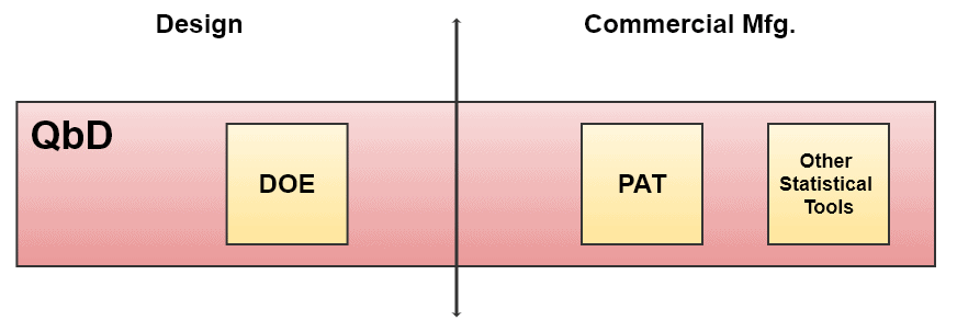 Overall Quality by Design Approach
Quality by Design Lifecycle Management
Lifecycle management involves the management of phases from the creation of a product to its disposal.
Apart from the FDA, ICH (International Conference on Harmonization) and ISO (International Organization for Standardization) have described the Quality by Design approach.
- ICH Q8 – Pharmaceutical Development
- Defines Quality by Design as: “A systematic approach to development that begins with predefined objectives and emphasizes product and product understanding and process control based on sound science and risk management.”
- Introduces the concept of Design Space as: “The multidimensional combination and interaction of input variables and process parameters that have been demonstrated to provide assurance of quality.”
- ICH Q9 – Quality Risk Management
- Define Risk as: “The combination of the probability of occurrence of harm and severity of that harm.”
- The goal is: “To ensure consistent quality throughout the product lifecycle.”
- Tools Suggested
- FMEA (Failure Mode Effect Analysis)
- FMECA (Failure Mode Effect and Criticality Analysis)
- Fault Tree Analysis
- Hazard Analysis and Critical Control Points (HACCP)
- Preliminary Hazard Analysis (PHA)
- Risk Rating etc.
- ICH Q10 – Pharmaceutical Quality System
- Defines how quality can be assured using a Quality Management System
- Requires QMS to cover the entire product lifecycle
- ISO 14971 – Medical Devices – Application of Risk Management to Medical Devices
For additional information on this, refer to the ICH or ISO websites.
Why Quality by Design (QbD)?
Because it helps to
- Maintain product quality throughout the manufacturing
- Optimize productivity and cost
- Reach zero market recalls
- Detect and control the variations
- Recognize the impact of CPPs on CQAs
1.1 Design of Experiments (DOE)
The Quality by Design concept includes the use of various tools to facilitate decision-making. DOE is one of them.
This smart decision-making tool identifies factors that influence a process or product response that pose a high risk. The goal is to develop and implement the design space.
To accomplish this requires a step-by-step process from selecting an objective to conducting multiple runs until you:
- Capture the data successfully
- Do analysis
- Conclude
When to Perform DOE?
DOE may be performed:
- To identify and mitigate potential risks during technology transfer.
- To better understand the process and product performance is required through Quality by Design.
DOE Flowchart
The following diagram shows the flow of different activities for DOE in QbD.
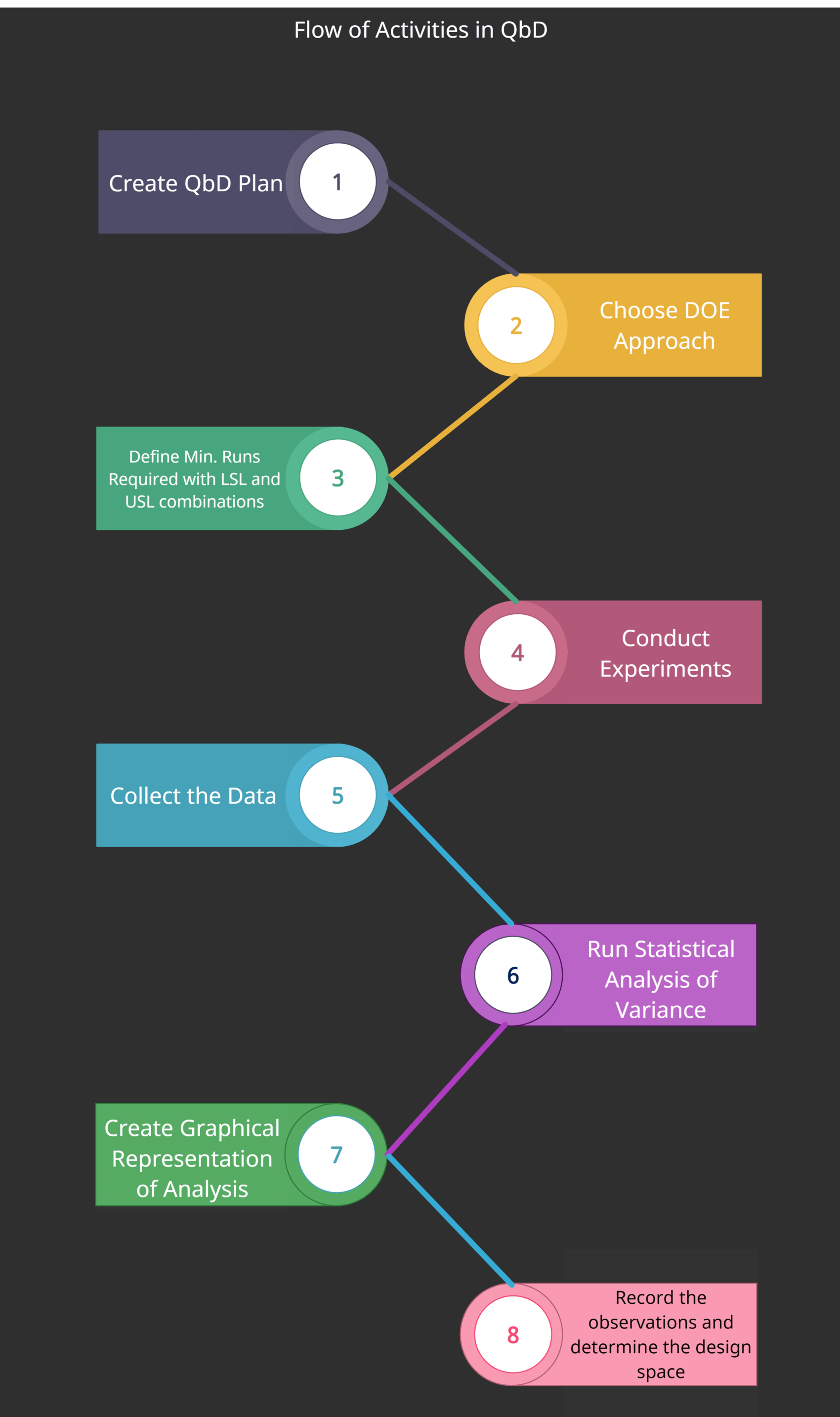 DOE activities through QbD
- Create a Quality by Design plan
- Choose your DOE Approach
- Define the minimum number of experiments required to investigate the variations including LSL and USL combinations
- Conducting experiments
- Collecting the data
- Run statistical analysis of variance
- Create a graphical representation of the analysis
- Record observations and determine the design space
This is an efficient tool for data collection and supports process optimization. It tests the magnitude of the effects and their suitability with the QbD.
When the design space within DOE is successfully established, small components of that process are the next target for better process control, based on statistical results from DOE. This is called Control Space.
Control space is a smaller zone in the design space explaining the commercial operation limits. Changing the parameters within the control space is considered acceptable for desired quality. See the diagram above, “Overall Quality by Design Approach”.
Though this looks straightforward, it requires collaborative efforts from SMEs and CFTs to taste the success in Quality by Design.
1.2 Process Analytical Technology (PAT)
This is another excellent approach to demonstrate Quality by Design. Unlike DOE, PAT provides a commitment to process control in real-time where ‘analytical’ terms account for chemical, physical, biological, and microbiological properties.
The FDA states, “A desired goal of the PAT framework is to design and develop well-understood processes that will consistently ensure a predefined quality at the end of the manufacturing process. Such procedures would be consistent with the basic tenet of quality by design and could reduce risks to quality and regulatory concerns while improving efficiency.”
To achieve this testimonial, industries adapt the following measures as improvements.
- Mitigating and preventing scraps/rejects/re-processing
- Improved process automation
- Improved production capacity
- Reduced process cycle times for better productivity
Process understanding is one of the aspects of PAT where a process is considered to be well-understood when:
- All critical sources of variation are identified and described
- The process itself manages variability
- Product quality attributes in the design space are predicted accurately and reliably
Drug manufacturing is a complex process. At different stages of manufacturing, the product either changes the physical or chemical attributes.
Well, chemical attributes are easy to detect analytically for products and raw materials.
But measuring physical attributes is a challenge in Quality by Design. Variability in only some of them may affect the end product quality.
PAT Approach
To facilitate process understanding and improvement, the FDA laid down 4 different approaches for the PAT framework:
- PAT Tools
- Multivariate Tool for Design, Data Acquisition and Analysis
- Process Analyzers
- Process Control Tools
- Continuous Improvement and Knowledge Management Tools
- Risk-Based Approach
- Integrated Systems Approach
- Real-Time Release
They assist the manufacturer to propose and implement innovative manufacturing and quality assurance systems.
The FDA encourages this and has also developed a regulatory strategy to consider such proposals such as:
- PAT Team approach for CMC (Chemistry, Manufacturing, and Controls) Review and cGMP inspections
- Joint training and certification of PAT review, inspection, and compliance staff
- Scientific and technical support for PAT review, inspection, and compliance staff
- Recommendations as per PAT guidance
The goal of FDA’s PAT activities is in line with the regulations that:
- Improves the scientific basis for establishing regulatory specifications
- Promotes continuous improvement
- Improves manufacturing along with product quality
Let us discuss some of the tools that will help to enhance the QbD in drug operations.
2. Lean and Six Sigma
Process variation is an undesired phenomenon.
Lean and Six Sigma (6σ) can work independently or together to minimize the variations. Also, they may be considered as part of Quality by Design or individual tools to improve the process ultimately.
Six Sigma (6σ) is a systematic approach to improve the process which uses statistical tools and techniques for analysis and process improvement. When added to a partnering method like Lean, Six Sigma (6σ) helps even more in eliminating the undesired operations systematically.
Sigma (σ) term indicates a mathematical approach, the standard deviation. It is a measure of variation.
The goal of Six Sigma (6σ) is to measure, minimize, and eliminate variations or defects. Therefore, it gets even more critical when dealing with the uncertainties in process design.
Once you measure, you identify. Once you identify, you improve. Once you improve, it gets recognized. Once recognized, you make it a habit.
2.1 Lean
Objectives:
- Creating value and reducing waste
- Improve product delivery
- Quality and productivity
- Reduce inventory
- Reduce Process Cycle Time
Tools and techniques that follow Lean principles:
Value Stream Mapping (VSM)
It is the way of mapping a process that enables the organization to identify and reduce the waste which does not add value to either the product or the process.
Typically depicts the flow of activities by operations, duration, and cost of each activity.
Kaizen (Kai: Change, Zen: Good)
It is an improvement tool to drive the overall effectiveness within the organization. As its name suggests, it is about bringing the change for the good.
“5s”
It is a technique to improve housekeeping and the working environment.
It incorporates 5s as:
- Seiri – Sorting
- Seiton – Set in order
- Seiso – Sweep
- Seiketsu – Standardize
- Shitsuke – Sustain
Gemba Walks
Actually a Genba but romanized to Gemba is a Japanese term. In lean practices, the Gemba refers to the actual place where value is created.
For example,
- Shop floor is Gemba for manufacturing
- Kitchen is Gemba for a restaurant
- Operation theater is Gemba for a hospital
More popularly known as “Gemba walks” meaning in terms of pharma:
- Visiting the shop floor
- Understanding the work flow
- Asking questions
- Respecting the operators and learning from them
Management staff un-usually do Gemba walks to identify the wastes in the process activities to streamline the operations at the actual place rather than discussing on the table.
Mistake Proofing (Poka-Yoke)
It is a fail-safe mechanism that prevents the process from generating defects.
QFD (Quality Function Deployment)
It is an approach to deal with the customer needs to make them satisfactory. There are different QFD matrices for customer quality expectations in comparison with the organizational functions such as:
- Requirement Matrix – Customer Requirements
- Design Matrix – Design Requirements
- Product Characterization Matrix – Engineering Design
- Manufacturing Matrix – Product Characteristics
- Control Matrix – Manufacturing Operations
Kanban
It is an inventory optimization technique based on simple parts movement based on boxes from one workstation to the other.
Moving to Pull
It is a technique to work or manufacture as per market demand, reducing overhead rate and storage costs.
In the end, it’s all about philosophy, mindset, and culture.
Lean thinking has a set of principles used to create and deliver the maximum value to the customer with the least resource consumption.
2.2 Six Sigma (6σ)
Objective
- Controlling the input variations to reduce the output variations, eventually delivering a consistent product quality.
- To fast-track process improvements systematically without hampering customer relationships.
- Dealing effectively one factor at a time.
Tool – DMAIC
Let’s look at this shortly.
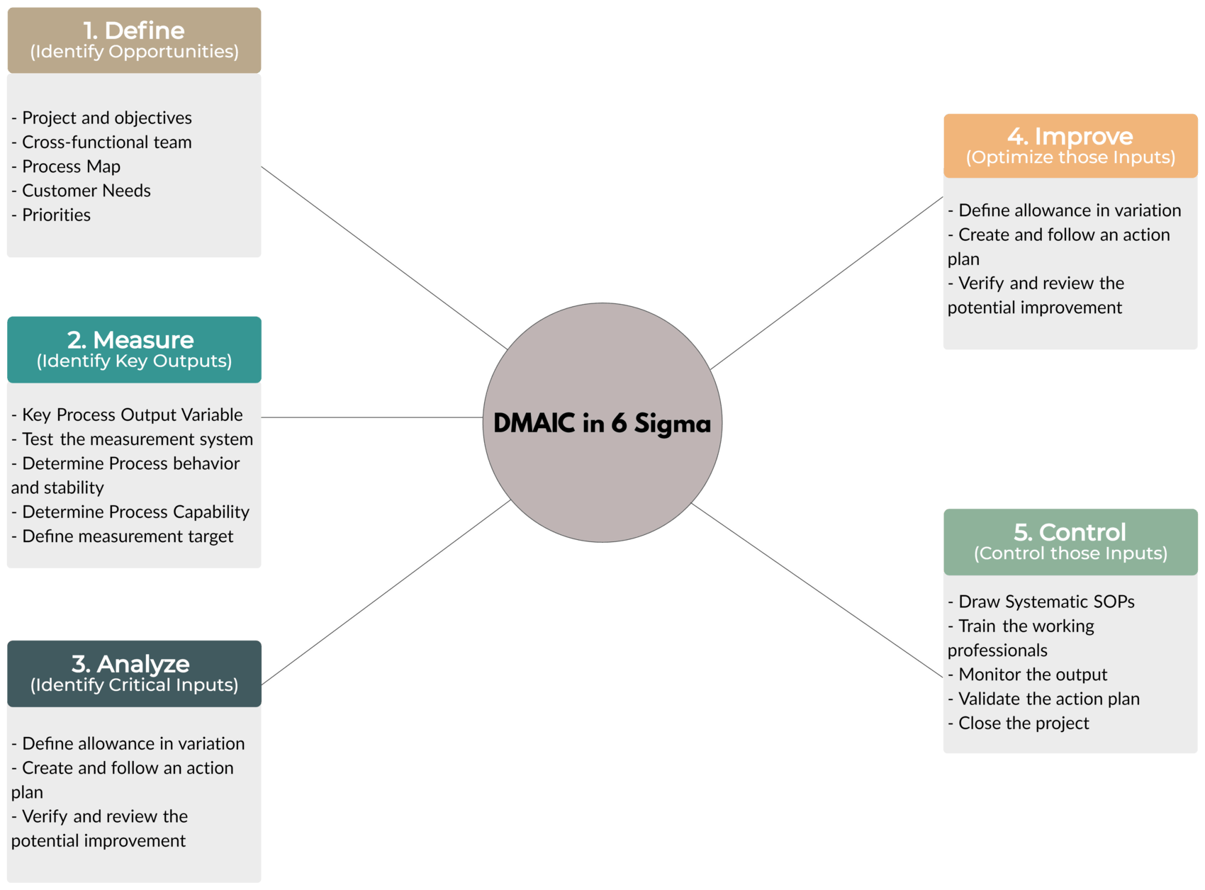 DMAIC Tool in 6-Sigma
- Define – Identify Opportunities
- Define the project and objectives
- Define CFT (Cross-Functional Team)
- Create a Process Map
- Recognize Customer Needs
- Define Priorities and update Project Charter
- Measure – Identify Key Outputs
- Recognize Key Process Output Variable
- Test the measurement system
- Find out the process behavior (e.g. Stability)
- Determine Process Capability
- Define the target for measurement
- Analyze – Identify Critical Inputs
- Fishbone Diagram
- Funneling
- Root Cause Analysis
- Review and finalize critical process inputs
- Improve – Optimize those Inputs
- Define the allowance in variation
- Create and follow an action plan
- Verify and review potential improvements
- Control – Control those Inputs
- Draw systematic SOPs (Standard Operating Procedures)
- Train the working professionals
- Monitor the output
- Validate the action plan
- Close the project file
Though Six Sigma (6σ) principles look simple, it requires very close monitoring and a thorough understanding of every activity being performed.
Before implementing six sigma, the following are the six sigma certification levels:
- Champion – Management Leader
- Master Black Belt – Who identifies the project and acts as a supporting function for Champion
- Black Belt – Full Time, Complex Role and a Key Project Driver
- Green Belt – Part-Time, non-complex support function for Black Belt
- Yellow Belt – Supporting team that collects data and performs basic analysis
- White Belt – Same role as Yellow Belt in training mode
3. Process-Failure Mode Effect Analysis (pFMEA)
Risk Management is also covered under Quality by Design but let’s see it broadly here.
pFMEA is a Quality Risk Management (QRM) tool that allows the manufacturer to anticipate, identify, prevent, or address the failure even before its occurrence.
It is therefore a product life-cycle document for process validation that shows the roadmap for failure management.
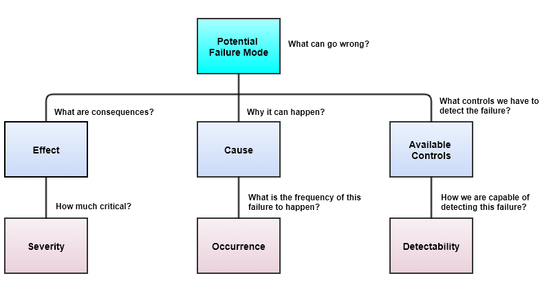
The below matrix shows the example of pFMEA.
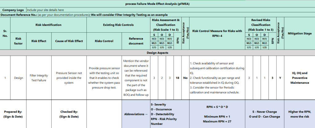 pFMEA Matrix and subsequent terminologies
(Zoom-in OR Open image in new tab for easy reading)
Once we identify Severity (S), Occurrence (O), and Detectability (D), there are 8 steps to apply pFMEA.
RPN = S x O x D
Identification of Severity (S), Occurrence (O), and Detectability (D)
 Risk Rating Flow (1 being least and 3 being maximum on basis of scale 1 to 3)
Steps to apply pFMEA
- Select a process to analyze
- Form a Cross-Functional Team
- Define a process description
- Identify potential risks
- Prioritize issues that impact either process or product quality directly or indirectly
- Target big issues first and bottlenecks prior to mitigation
- Propose and Implement risk mitigation actions
- Measure the success of the process (either during process validation stages or as applicable)
As described above, ISO 14971:2019 – Medical devices — Application of risk management to medical devices also follow the same pattern for risk identification and mitigation.
The Difficulty of FMEA
In this, the SOD is multiplied to give the RPN number and defines the Risk Acceptance Criteria as “the higher the RPN, the more the risk”.
Though this sounds logical, it is somehow not. Because the two factors are dynamic in this process i.e. O and D. If you reduce D, the RPN number will decrease but O is still at risk of being undermined due to this RPN calculation.
Many industries are now treating each component of the SOD separately instead of RPN-based decision-making. That sounds more realistic.
4. Process Capability
Process Capability is a statistical study to expedite how all the measurements fall inside the pre-defined specification limits. It may be a part of Quality by Design.
The capability of a process is generally measured in terms of Cp value.
When a Cp≥1.33 (i.e. 4 Sigma), a process is believed to be capable of satisfying the customer needs in drug manufacturing.
Let us see shortly the different terms used to measure Process Capability.
Short-Term and Long-Term Approach
Process Capability (Cp)
Process Capability is a simple approach to show the process is capable of resulting in a product that will fall within its pre-defined specification limits.
Cp = (USL – LSL) / 6σ
where,
USL – Upper Specification Limit
LSL – Lower Specification Limit
6σ – Estimated noise of a stable process
Process Capability Index (Cpk)
Process Capability Index (Cpk) is an advanced approach to demonstrate that the process is capable of consistently and precisely falling within its pre-defined specification limits.
Often, Cpk is a simple number. A common term for this approach is called process centering. Meaning, how well a process is able to establish its outcome within the center of its specification limits.
Cpk = min (CpkU, CpkL)
where,
CpkU = (USL – Mean) / 3σ
CpkL = (Mean – LSL) / 3σ
Using Cp and Cpk together shows us how capable a process is and whether it is centered or not. In pharmaceutical language, this approach resembles the Quality by Testing (QbT) approach.
Long-Term But Retrospective Approach
Process Performance Index (Pp)
Process Performance is a measure of overall process variability with respect to customer CTQs, unlike process capability.
Pp = (USL – LSL) / SD
where SD – overall variability (Standard Deviation for Common+Special Cause of Variations)
Min. Process Performance Index (Ppk)
This shows how a process has been performed in the past, irrespective of its stability.
Ppk = min (PpkU, PpkL)
where,
PpkU = (USL – Mean) / 3σ
PpkL = (Mean – LSL) / 3σ
For all the above terminologies, k stands for centering factor.
Process Capability vs. Six Sigma (6σ)
Cpk ValueSigma LevelSigma %Rating0.333168.27Worst0.667295.45Poor1399.73Kind of Capable1.333499.9936Capable1.667599.99994Better2699.9999998The BestComparison Between Process Capability Index and Related Sigma Levels
Difference between Cpk and Ppk
CpkPpkShort-term approachLong Term ApproachHow this process will be capable in the futureHow was the process capable in the pastRequires a process in the state of controlState of control is neither required nor possible as the process has already occurredTells us about how the variation will affect the process capability in terms of customer CTQsTells us about the extent of process variationsNeeds data sub-grouping such as machines, operators, shifts, floors etc.This applies to the whole process
5. “5 Why Analysis”
Often, the defects or failures that occur within a manufacturing environment are attributed to one or various reasons.
Instead of thinking about what’s the root cause of an issue, asking “why” helps in the systematic investigation.
5 Why Analysis is an event-based tool for digging out the root cause based on Lean thinking.
Though it contains the number 5, it does not mean that it must contain 5 whys. The number may be less or more based on the magnitude of the event.
The important thing is how relevant your whys are and how fundamentally you investigate the root cause of an event.
A typical 5-why analysis skeleton looks like this:
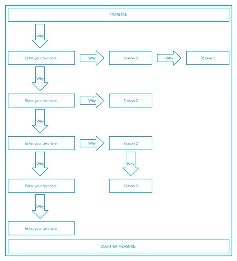 5-Why Analysis
The system can then be implemented such as Good-Save/Near-Miss to guide the employees in sharing the feedback and come up with preventive plams.
So, this helps to identify the opportunity to improve through systematic Q&A.
Sometimes, 5 Why Analysis doesn’t go as expected if used as the only tool to investigate the root cause and may need to be used in conjunction with another suitable tool.
In fact, no root cause identification tools are every time effective.
Sometimes unintentionally, industries misuse them to allocate the root cause to the human error which is a trending controversy nowadays.
6. Fault Tree Analysis
The Fault Tress Analysis is a graphical tool to investigate the roots of the occurred events such as defect, failure, deviation, incident, non-conformance, etc.
The structure of this tool resembles a tree that we see above the ground as an “event” while underground roots we can not see as “potential reasons” for the event.
The layers of different investigative questions can lead to one or more reasons for the resultant event. To understand how this tool can help identify the root cause of an event, let us see an example.
Imagine an event where a batch has failed on its final moisture requirements post drying. A fault tree diagram for this example could be developed something like this:
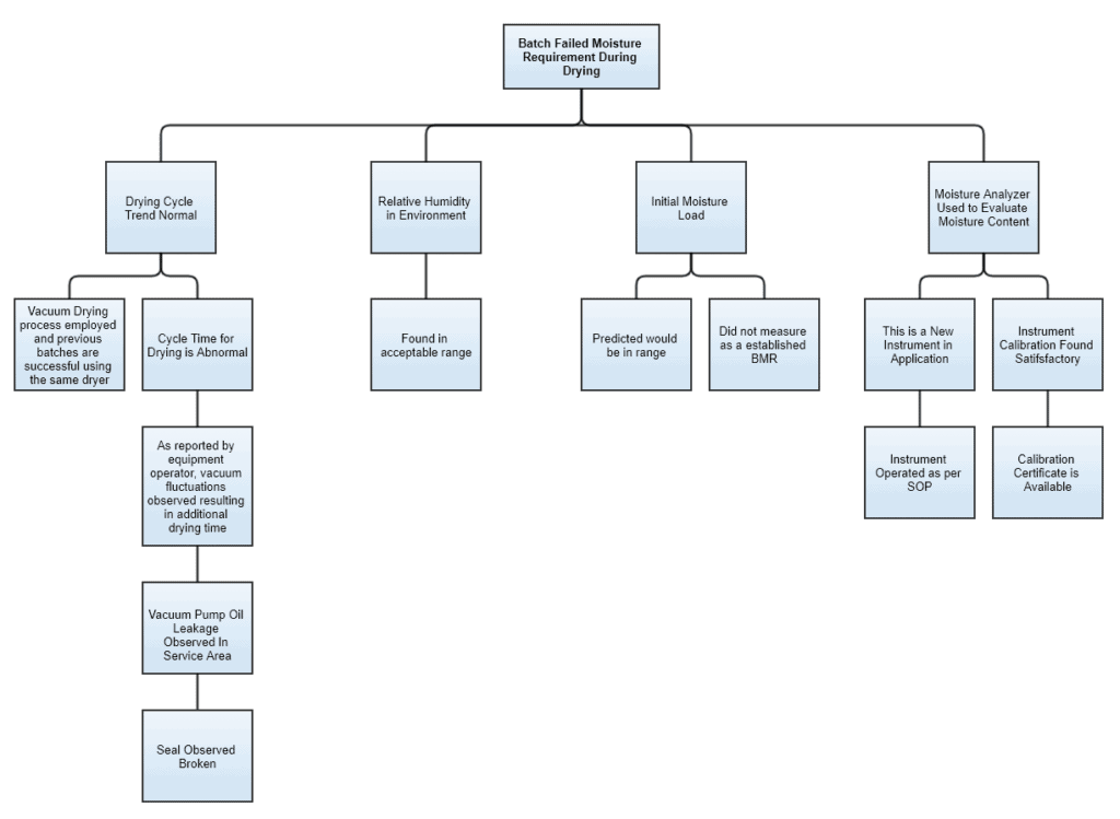 Fault Tree Analysis
You see, the first layer of the tree has some critical parameters and the branches are developed along with the progress of the investigation.
Environmental and test instrument conditions appear normal. Whilst “Cycle Time” under “Drying trend” and “Initial Moisture” has loose ends.
After investigating further, we can see the root cause possibly based on two aspects i.e. technical and documentation. Technical in terms of the broken seal. Documentation because BMR failed to capture moisture-related information before drying.
Once we identify these causes, corrective and preventive actions (CAPA) should be proposed, implemented, and verified for actual prevention in the future.
For a broken seal, documents should be checked for their validity and replacement timelines. While for BMR correction, the quality event should be initiated as per the local procedures.
Fault Tree Analysis can help identify the root cause for such events. Sometimes, this tool is used along with other tools to streamline the investigation process.
7. Fishbone Diagram / Ishikawa Diagram / Cause and Effect Diagram
The cause and effect diagram has two sides. The right side is categorized as Effects which records the burning issues while the left side is categorized as Causes which records the major causes of those issues.
A Cross-Functional Team (CFT) is formed to identify, expedite, and chart out the potential causes. This team may be similar to the one defined in QbD.
Serious causes should occupy a major portion of the diagram. This diagram is best suitable for the management to effectively understand the real burning issues within their organization.
Once the dominant causes are marked as bone of fish, the next step is to identify and allocate the 6M’s to each cause i.e.
- Man
- Machine
- Method
- Measurement
- Material
- Mother Nature
CFT then helps the facilitator to sort out those causes, becoming the main bones of a fish. The below diagram represents a typical representation of the fishbone method.
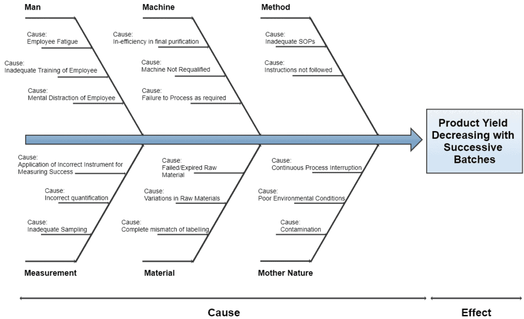 Example of Fishbone/Ishikawa/Cause and Effect Diagram
8. Gage R&R Study
Gage R&R is used in Measurement System Analysis (MSA) and is a quantitative assessment of variation in a measurement system compared to the total variation of the process in terms of repeatability and reproducibility.
Well, better if we differentiate them now.
RepeatabilityReproducibilityShort-term variabilityLong-term variabilityIn-built precision of the instrument or the device itselfVariations are external conditions like environment, operators, etc.This is a residual errorThis is the sum of variations due to personnel-related changesDifference between Repeatability and Reproducibility
Exactly speaking, Gage R&R validates the measurement system and determines % of total variation with respect to gage and % of tolerance a gage variation has.
To deliver effective Gage R&R results, exhaustive runs are required to get all the variability sources precisely. Hence, it’s impossible to estimate the process variability at the development stage because of the small number of lots.
To elaborate on the above in a simple way, Gage R&R enables the six sigma practitioners to label their process Six Sigma without producing the defects of more than 3.4 per million opportunities.
Gage R&R comes under the Measurement (M) Category according to the DMAIC tool in the six sigma methodology.
Gage R&R studies have been used to investigate chemical analytical methods for uniformity at different stages of pharmaceutical manufacturing i.e. APIs, Formulations, and Injectables.
Total Variability = Process Variability + Measurement Error (Gage Variability)
This method can be considered for new Test Method Validation as well as already validated measurement systems within the pharmaceutical industries. This includes both destructive and non-destructive testing.
Sometimes, this is not considered quality by design tool because certain measurements fall outside the QbD scope.
Gage R&R can be calculated by 3 different techniques.
- Average and Range Estimate (Long AIAG)
- Range / Measurement Process Evaluation MPE (Short AIAG)
- Analysis of Variation (ANOVA)
Here, AIAG stands for Automotive Industry Action Group. If you are interested in additional information on this, you can visit SPC for Excel where they’ve got a plethora of information on Gage R&R.
Conclusion
Quality by Design is a vast space and a demanding side of making quality drugs. Every tool that we discussed above has its pros and cons. Some of these tools partially or fully come under QbD space based on situations.
We’ve seen an overview of each tool’s working mechanism and its expected outcome. Intelligent use of these tools effectively improves productivity and product quality.
Now I’d like to hear from you:
- What QbD tools do you use to improve your product quality?
- Are you following a statistical route?
- Or maybe you follow quality risk management.
Let me know by leaving a comment below right now.