
Wireless VoIP QoS Best Practices
This article is a guide to optimize Quality of Service (QoS) for wireless Voice over IP applications on Meraki MR wireless access points. Voice over IP (VoIP) has replaced telephones in enterprise networking with IP-based phones. While the majority of desk phones using VoIP require ethernet, there are many voice applications and wireless VoIP phones that operate over WiFi.
The Meraki MR series of WiFi access points have been tested by Cisco Meraki to provide the highest quality VoIP experience when using Cisco Jabber, Microsoft Lync, Microsoft Skype for Business, Broadsoft, Cisco 7900 Series phones, SpectraLINK phones, Ascom phones, Cisco phones, and Apple iPhones. This guide will provide recommendations for optimizing voice quality followed by product specific recommendations.
After making the changes exactly as described in this guide, we see a significant improvement in voice quality. The MOS score approaches 3.9, the packet loss is near zero, and the jitter is consistently below 6 milliseconds and always below 12 milliseconds. As the call starts, traffic shaping kicks in automatically with prioritization and QoS tagging. A speed test was performed with no impact to the voice traffic – packet loss increased to 0.5% during the congestion.
With the default settings on the MR, we see the baseline for quality. Voice calls with Lync on this network would be acceptable to some users, but not acceptable to others. The results of the Lync testing show that the Network Mean Opinion Score (MOS) drops below 3.5. Values values dropping below 3.5 are termed unacceptable by many users. The packet loss jumps to 8 percent during a period of network congestion simulated by running a speed test. Jitter fluctuates from 12 milliseconds to over 36 milliseconds. Cisco recommends a target of 10 ms of jitter and no more than 50 ms of jitter. Jitter is handled using buffering in voice/video applications, adding a small delay. The human ear normally accepts up to about 140 milliseconds of delay without noticing it.
By combining this guide with best practices for configuring your client device configuration, application servers, WAN links, and wired network, you can measure and improve quality voice end-to-end. For more information on configuring your wired network to support Voice, please visit the article on Configuring MS Access Switch for Standard VoIP deployment article.
To develop this guide, we performed testing using Microsoft Lync’s Pre-Call Diagnostics Tool. The endpoints used during testing were Macbook Pros running Office 365’s Cloud-hosted Skype for Business Online, also known as Lync Online. All tests were performed while connected to an MR32 access point inside Meraki’s headquarters in San Francisco, a high density corporate WiFi network. This tool measures 3 key metrics for voice quality:
By following this guide, you can significantly improve quality of service for the wireless voice applications and reduce or eliminate dropped calls, choppy speech, fuzzy speech, buzzing, echoing, long pauses, one-way audio, and issues while roaming between access points.
All Meraki MR series access points support the most recent 802.11 standards implemented to assist devices to roam between access points and ensure voice calls maintain a quality user experience.
A Cisco Meraki wireless network has the intelligence built-in with deep packet inspection to identify voice and video applications and prioritize the traffic using queuing and tagging to inform the rest of the network how to handle your voice traffic. Below is a summary of the best practices to provide the best voice quality over wireless.
For more guidelines on site surveys read our article on Performing a Wireless Site Survey . For more detailed guidelines on designing RF specifically for Cisco Voice over WiFi please read Cisco’s Voice over WLAN Guide .
Pre-site surveys are useful for identifying and characterizing certain challenging areas and potential sources for interference, such as existing WiFi networks, rogues, and non-802.11 interference from sources such as microwave ovens and many cordless telephones. Post-site surveys should be performed at least 48 hours after installation to allow the network to settle on channel and power settings.
The design and layout of access points is critical to the quality of voice over WiFi. Configuration changes cannot overcome a flawed AP deployment. In a network designed for Voice, the wireless access points are grouped closer together and have more overlapping coverage, because voice clients should roam between access points before dropping a call. Designing with smaller cells and lower power settings on the access point are key elements to ensure the overlapping coverage from neighboring APs/cells. Set a clear requirement based on the device type when performing a survey.
Mục lục
Network Configuration
Making the changes described in this section will provide a significant improvement in voice quality and user satisfaction by following the best practices for configuring your SSIDs, IP assignment, Radio Settings, and traffic shaping rules.
Add a Dedicated Voice SSID
Voice optimization typically requires a different configuration including access control and traffic shaping to address device specific recommendations. You should create a separate Voice SSID for devices dedicated to voice applications. While this is not a requirement, we recommend to create a separate network to follow this guide. In networks with VoIP handsets from two different manufacturers, it is common to create two voice SSIDs.
If you plan to deploy more than 4 SSIDs please read our guide on the Consequences of Multiple SSIDs.
Authentication Type
Voice over WiFi devices are often mobile and moving between access points while passing voice traffic. The quality of the voice call is impacted by roaming between access points. Roaming is impacted by the authentication type. The authentication type depends on the device and it’s supported auth types. It’s best to choose the auth type that is the fastest and supported by the device. If your devices do not support fast roaming, Pre-shared key with WPA2 is recommended. WPA2-Enterprise without fast roaming can introduce delay during roaming due to its requirement for full re-authentication. When fast roaming is utilized with WPA2-Enterprise, roaming times can be reduced from 400-500 ms to less than 100 ms, and the transition time from one access point to another will not be audible to the user. The following list of auth types is in order of fastest to slowest.
- Open (no encryption)
- Pre-shared key with WPA2 and Fast roaming
- WPA2-Enterprise with Fast roaming
-
Pre-shared key with WPA2
- WPA2-Enterprise
WPA2 only for Encryption Mode
Voice devices can benefit from having a single type of encryption used. By default, SSIDs on Cisco Meraki access points that are configured as WPA2 will utilize a combination of both WPA1 TKIP and WPA2 AES encryption. WPA2 (AES) is recommended and required in order to utilize caching or fast roaming. The WPA encryption setting is SSID specific, and can be found on the Wireless > Configure > Access control page.
- If all Voice devices support WPA2, the ‘WPA2 only’ option is recommended for Voice over IP devices.
- If the device does not support AES, it is also possible to force TKIP only. Please contact Cisco Meraki support to configure this option.
For step-by-step instructions on changing the WPA encryption mode, see our document on Setting a WPA Encryption Mode.
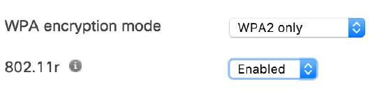
802.11r fast roaming
Enabling 802.11r is recommended to improve voice quality while roaming. The 802.11r standard was designed to improve VoIP and voice applications on mobile devices connected to Wi-Fi, in addition to or instead of cellular networks. When mobile devices roam from one area to another, they disassociate from one access point and reassociate to the next access point. Enabling 802.11r benefits VoIP devices by reducing the roaming time spent changing between access points. Some client devices are not compatible with Fast BSS Transition (802.11r). You may wish to check your devices for compatibility.
This feature can be enabled from the Configure > Access control page under Network access > 802.11r. If this option does not appear, a firmware update may be required. For more details on 802.11r, refer to our guide on Fast Roaming Technologies
It has been determined that configuring an SSID with WPA2-PSK and 802.11r fast roaming poses a security risk due to a vulnerability. The vulnerability allows potential attackers the ability to obtain the PSK for the SSID when a client fast roams to another AP. While 802.11r does improve VOIP quality as the time for the necessary re-association process to the next AP is reduced, it is not recommended to use 802.11r fast roaming at this time with an SSID using WPA2-PSK.
You can read more on the 802.11r with WPA2-PSK vulnerability on this blog post.
Layer 2 and Layer 3 Roaming
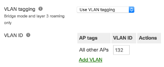
Bridge mode is recommended to improve roaming for voice over IP clients with seamless Layer 2 roaming. In bridge mode, the Meraki APs act as bridges, allowing wireless clients to obtain their IP addresses from an upstream DHCP server. Bridge mode works well in most circumstances, particularly for seamless roaming, and is the simplest option to put wireless clients on the LAN. To configure the client IP assignment modes please refer to our document on SSID Modes for Client IP Assignment.
When using Bridge mode, all APs on the same floor or area should support the same VLAN to allow devices to roam seamlessly between access points. Using Bridge mode will require a DHCP request when performing a Layer 3 roam between two subnets. For example, when a user on a VoIP call roams between APs on different VLANs without layer 3 roaming, the user’s session will be interrupted as the external server must re-establish communication with the client’s new IP address. During this time, a VoIP call will noticeably drop for several seconds, providing a degraded user experience.
Large wireless networks with multiple VLANS per floor may require IP session roaming at layer 3 to enable application and session persistence while a mobile client roams across multiple VLANs. With layer 3 roaming enabled, a client device will have a consistent IP address and subnet scope as it roams across multiple APs on different VLANs/subnets. If Layer 3 roaming is required on your network, please refer to our article on Layer 3 Roaming.
Note: It is strongly recommended to consult with a Cisco Meraki SE or Cisco Partner when considering layer 3 roaming options.
NAT mode is not recommended for Voice over IP: With NAT mode enabled, your devices will request a new DHCP IP address on each roam. Moving between APs in NAT mode will cause the connection to break when moving AP to AP. Applications requiring continuous traffic streams such as VoIP, VPN or media streams will be disrupted hen roaming between APs.
Segregate Traffic on a Voice VLAN
Voice traffic tends to come in large amounts of two-way UDP communication. Since there is no overhead on UDP traffic ensuring delivery, voice traffic is extremely susceptible to bandwidth limitations, clogged links, or even just non-voice traffic on the same line. Separating out your voice traffic allows it to function independently of other network traffic, and allows for more granular control over different types of traffic.
If a voice VLAN is specified on a Meraki MS switch, the port will accept tagged traffic on the voice VLAN. In addition, the port will send out LLDP and CDP advertisements recommending devices use that VLAN for voice traffic. The VLAN tagged on the wireless access point should match the Voice VLAN on your wired network. For more information, please visit the article on Configuring MS Access Switch for Standard VoIP deployment.
Band Selection
The 2.4 GHz band has only 3 channels that do not overlap, while the 5 GHz band has up to 19 individual channels in the US. A wireless network will provide the best quality of service for wireless voice when designed correctly to support 5 Ghz coverage for voice. This can be configured under Access Control > Wireless options > Band selection > ‘5 GHz band only’. After configuration, testing should be performed in all areas of your environment. If you do not have proper 5 GHz coverage after a post-install site survey, you can manually increase the power on the 5 GHz radio in Radio Settings > Channel Planning.
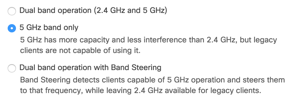
If you do not have a dedicated Voice SSID, enable ‘Dual-band with band steering’ to enable your voice devices to use both 2.4 GHz channels and 5 GHz. Devices will be steered to use the 5 GHz band. For more details refer to the Band Steering Overview article. With a dual-band network, client devices will be steered by the network. However, to improve voice quality, please follow our guide on configuring wireless band preference on client devices.
If you have devices that only support a 2.4 GHz network such as 802.11bgn devices, please contact Meraki Support to enable a 2.4 GHz only network.
Minimum Bitrate
For Voice networks, 12 Mbps is recommended as the minimum bitrate. Increasing this value requires proper coverage in the RF planning. An administrator can improve the performance of clients on the 2.4 GHz and 5Ghz band by disabling lower bitrates. Adjusting the bitrates can reduce the overhead on the wireless network and also in some cases improve roaming performance.
The minimum bitrate is configured in Wireless > Radio Settings > RF Profiles > [Profile Name] and can be set on per band or on per SSID basis.
Bandwidth Limits
Consider placing a per-client bandwidth limit on the rest of your network traffic. Prioritizing voice will have a greater impact if all other applications are limited. For more details refer to the article Configuring Bandwidth Limitations and Enabling Speed Burst on Wireless Networks.
- Go to Wireless > Configure > Firewall & traffic shaping and choose your SSID from the SSID drop down menu at the top of the screen.
- Set a ‘Per-client bandwidth limit‘ to 5 Mbps with ‘Speed Burst‘. This will apply to all non-voice application traffic. This step in the guide is optional.
- Set a ‘Per-SSID bandwidth limit‘ to unlimited.
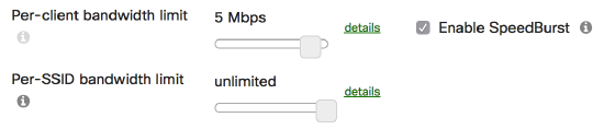
SpeedBurst enables a bursts of four times the allotted bandwidth limit for five seconds.
Traffic Shaping Rules
Use traffic shaping to offer voice traffic the necessary bandwidth. It is important to ensure that your voice traffic has enough bandwidth to operate. As such, traffic shaping rules can be implemented to allow voice traffic to use additional bandwidth, or limit other types of traffic to help prioritize voice traffic.
- Go to
Wireless >
Configure > Firewall & traffic shaping
and choose your SSID from the SSID drop down menu at the top of the screen.
- Click the drop down menu next to Shape traffic and choose
Shape traffic on this SSID
, then clickCreate a new rule
.
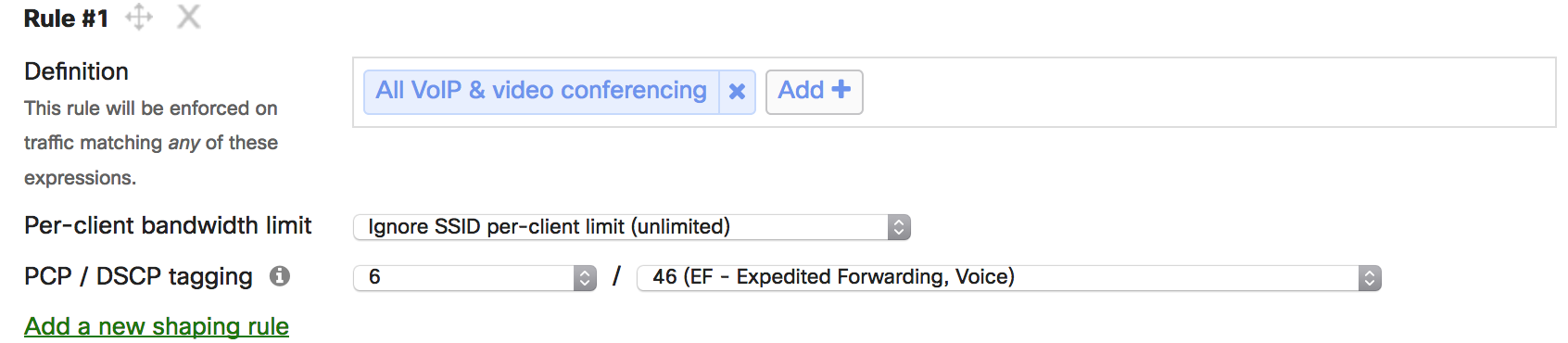
- Click Add + and select
‘All VoIP & video conferencing‘
- Set Per-client bandwidth limit to ‘Ignore SSID per-client limit (unlimited)‘ and click Save changes.
PCP, DSCP, and WMM mapping
Many devices support Quality of Service (QoS) tags to maintain traffic priority across the network. Meraki MR access points support WMM to improve the performance of real-time data such as voice and video. WMM improves the reliability of applications in progress by preventing oversubscription of bandwidth. WMM accomplished this by enhancing the prioritization of traffic using the access categories: voice, video, best effort, and background data. WMM has mapped values which can be found in this article. To configure correct mapping for PCP and DSCP values, the following steps should be followed:
- Go to Wireless > Configure > Firewall & traffic shaping and choose your SSID from the SSID drop down menu at the top of the screen.
- Under the traffic shaping rules, make sure Shape Traffic for this SSID is selected and that there’s a rule for
All voice & video conferencing.
- Set PCP to ‘6‘ or the setting recommended by your device/application vendor (Note that PCP values can only be changed if the SSID has VLAN tagging enabled. This ensures there’s a field to which the CoS value can be written).
- Set DSCP to 46 (EF – Expedited Forwarding, Voice) or the setting recommended by your device/application vendor.
Note: The DSCP tag, 46 (EF – Expedited Forwarding, Voice) maps to WMM Access Category AC-VO for Voice, Layer 2 CoS 6)
If no DSCP values are configured, the default DSCP to WMM mapping will be used. The access point does the mapping between the LAN’s Layer 2 priority and the radio’s WMM class. Below is table showing the mapping between common traffic types and their respective markings:
RFC 4594-Based Model
802.3 DSCP
802.3 DSCP [Decimal]
IEEE 802.11 Model [802.11e WMM-AC]
Voice + DSCP-Admit
EF + 44
46
Voice AC (AC_VO)
Broadcast Video
CS5
24
Video AC (AC_VI)
Multimedia Conferencing
AF4n
34, 36, 38
Video AC (AC_VI)
Realtime Interactive
CS4
32
Video AC (AC_VI)
Multimedia Streaming
AF3n
26, 28, 30
Video AC (AC_VI)
Signaling
CS3
40
Video AC (AC_VI)
Transactional Data
AF2n
18, 20, 22
Best Effort AC (AC_BE)
OAM
CS2
16
Best Effort AC (AC_BE)
Bulk Data
AF1n
10, 12, 14
Background AC (AC_BK)
Scavenger
CS1
8
Background AC (AC_BK)
Best Effort
DF
0
Best Effort AC (AC_BE)
* n as used in place for the drop indication of assured forwarding matches values 1-3.
For QoS prioritization to work end to end, ensure that upstream networking equipment supports QoS prioritization as well. The PCP and DSCP tags applied on the wireless access point should match the wired network configuration to ensure end-to-end QoS. For more information, please visit the article on Configuring MS Access Switch for Standard VoIP deployment article.
Custom Traffic Shaping
If your voice traffic does not match the built-in application signatures or is not listed, you can create your own signature for traffic shaping.
- Add the IP and ports used by your servers hosting Microsoft Lync / Skype for Business, Jabber, Spark, or other voice application.
- In the Definition field click Add + and Custom expressions
- In the text field, enter the IP address of each of your voice servers for example 172.16.1.123 or a range of server IPs 172.16.1.0/24
- Also, add your servers as source addresses by using the CIDR notation localnet:172.16.1.123/32 for an individual server, or localnet:172.16.1.0/24 for a range of IPs.
- Click the Add + button again when finished.
- If you have a dedicated voice SSID and dedicated voice VLAN add the local subnet of the client devices.
- In the Definition field click Add + and Custom expressions
- In the text field, enter localnet:192.168.0.1/16 indicating the source subnet of your client devices in CIDRnotation.
- Click the Add + button again when finished.
- Set Per-client bandwidth limit to ‘Ignore SSID per-client limit (unlimited)‘ and click Save changes.